NOTE: Rick has been contacting me the last few years wondering if I wanted to sell the 4 X 4 back to him. I finally decided I needed a new trailer worse than the 4 X 4. So Rick and I made a deal and I sold it back to him. It was a great project and I really enjoyed working on it, but it’s back home where it belongs.
In December 2011, I saw an advertisement on a Cub Cadet forum for a 4 X 4 project tractor running gear on sale by Rick Beem. Rick had started to restore a Cub Cadet Original in 2000. In 2005 he changed the project to a FWA Cub Cadet and had run out of time to finish it. Following is a discussion of Rick’s work based on email conversations with Rick.
Rick had already put a lot of time and work into the project. He had purchased a mid-mount Massey Ferguson 1428 PTO. The Massey has a 45 tooth gear with a module of 2.5 mm and a pitch diameter of 122.5 mm.

He also purchased a 23 tooth gear with a module of 2.5 mm from Quality Transmission Components that mated with the Massey PTO gear. The gear had a 15 mm bore and a 57.5 mm pitch diameter. Rick used an EDM to cut an internal spline to fit the 10 spline, .978 inch O.D. pinion shaft of a Cub Cadet transmission. The gear was used to replace a spacer on the pinion shaft.

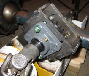
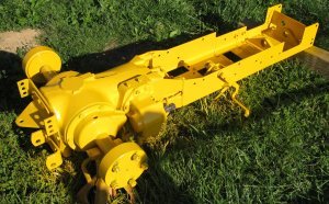
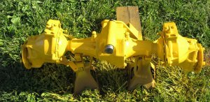
With the gear in place, Rick used a CNC mill to mill a cavity in the Cub Cadet transmission. He also machined the outer surface of the transmission to obtain a smooth, known profile. The given pitch diameters required a center distance of 90 mm. With that information and the outer profile of the gear box that was known, Rick used a CNC mill to machine an adapter to bolt the Massey PTO to the side of the Cub Cadet transmission.
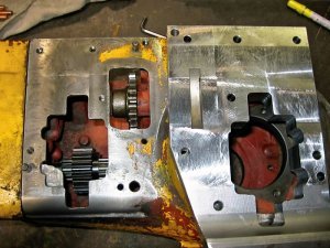
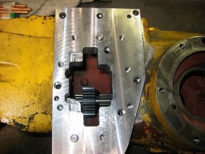
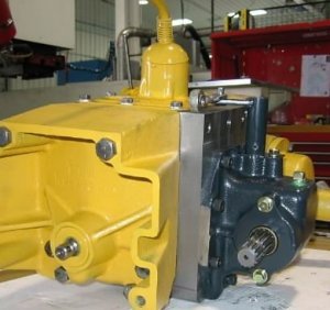
With the adapter in position, the PTO could be mounted to the side of the transmission.
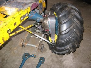
With the rear PTO completed, Rick turned his attention to the front end. Rick obtained a front wheel drive front end from a Kubota B6100.
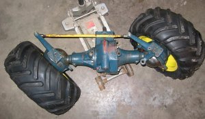
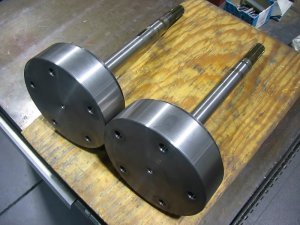
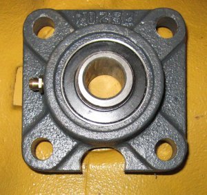
The Kubota front end came with a four bolt flange for mounting the wheels. Rick machined new flanges to permit the use of a standard 5 bolt wheel.

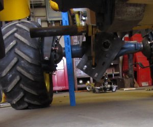
The first order of business was to make an adapter to mount the 4 X 4 axle under the Cub Cadet frame.
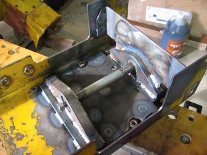

The location of the original steering arm knuckles on the Kubota front end prevented the installation of a tie rod. New knuckles had to be made to allow the tie rod to go beneath the Cub Cadet frame. Making the new knuckles wasn’t just a matter of finding something that would fit. In addition to the clearance problem, Rick had to take into account the Ackerman angle to achieve proper steerng. As Rick explains it,
“As applied to Tractors and how I understand it, if you were to draw an imaginary triangle from the pivot point of the front spindles to a point centered between the rear axle your tie rods ends should be on this line or just inside of it depending on use, tires, etc. etc. This point at the front is somewhat of a guess because of the (approx.) 10 degree camber here.
Having this geometry in the right range allows the inside front tire to turn sharper than the outside tire, so that the tractor will turn sharply without “shoving” one of the tires where it is trying not to go.”
The Kubota front end had a wider wheel spacing then the Cub Cadet. That required making a 1 ½ inch wide adapter for each rear axle to increase the width of the rear end.
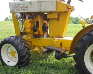
Rick’s plan was to replace the Original’s 7 hp engine with a Teledyne, a 4 cylinder, 6 hp Military engine that supposedly develops over 15 hp. To make room for the Teledyne, Rick extended the Original frame by 6 3/8 inches and added a second pulley to the clutch to handle the extra hp.

And, that’s where Rick ran out of time.
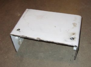
I met Rick just outside of Champaign, Illinois around the middle of January (2012) and we exchanged money and tractor. I purchased the tractor running gear complete with the Kubota front end and mounted Massey PTO. Additionally, Rick included a hood, seat, steering wheel, a specially made fender plate, and a box of miscellaneous parts and gaskets.
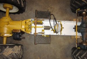
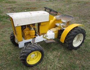
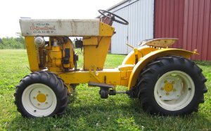
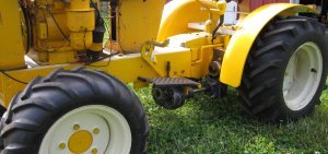
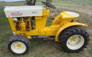
Rick’s intention was to use an extended hood on the longer frame. I wasn’t sure I’d like that look, so I started looking for alternatives to “disguise” the longer look. I assembled the tractor with parts I had and added a front winch to see what it would look like.
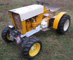
I still didn’t particularly care for the looks, but a survey of family and friends was pretty evenly split on whether I should shorten it or leave it extended. I decided I’d put that decision off for a while.
My problem was to get a drive from the rear PTO to the front pinion shaft of the Kubota front end. Additionally, the rear PTO turned too slow and in the wrong direction to drive the front end. I figured it would take a combination of a chain drive and gear box to get the correct speed and direction.
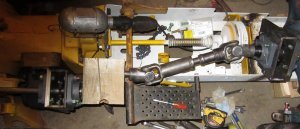
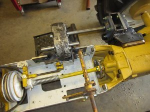
I only had to crawl under the tractor once to decide that wasn’t going to be a good way to figure this out. So, I removed the grill, hood, engine, seat, gear shift lever and fenders and flipped the tractor upside down for easier access.
The first order of business was to determine exactly how much the rear output had to be speeded up. Rick had given me an estimate of the order of magnitude but told me I needed to check it to be sure. I decided I’d check it by calculating the gear ratios as well as determining it experimentally.
I started by counting gear teeth. As mentioned previously, the gear Rick added to the Original pinion shaft had 23 teeth. It drove the 49 tooth gear on the Massey PTO which in turn drove a 21 tooth pinion. The pinion in the Original rear end has 10 teeth and the ring gear has 46 teeth. That gives a ratio of 5.038 for the rear end. That is, for one revolution of the rear wheel, the PTO shaft turns 5.038 revolutions.
For the Kubota front end the input pinion shaft has 6 teeth and the ring gear has 37. Additionally, the Kubota front end has a gear reduction at the wheel. The “wheel” gear has 25 teeth and the “wheel” pinion has 12 teeth. That results in a ratio of 12.847. That is, for one revolution of the front wheel, the front input shaft would have to rotate 12.847 times.
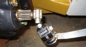
Before accounting for the different wheel circumferences for the front and rear tires, I decided I’d check those ratios experimentally to make sure I hadn’t miscounted the number of teeth on any of the gears. I used a counter that Rick had furnished to count revolutions.
For the rear end, 50 rotations of the rear wheel resulted in 252 rotations of the PTO shaft. That gives a ratio of 5.04 which agrees well with the calculated. For the front axle, 50 rotations of the front wheel, resulted in 642 rotations of the front input shaft. That gives a ratio of 12.84 which again agrees well with the calculated.
With the ratios nailed down, the different wheel diameters had to be accounted for. I used two methods to determine the circumferences. I wrapped a strap around the wheels and measured the length of the circumferences. For the rear wheel, I got a circumference of 70.25 inches and for the front wheel 55.75 inches. I also tried to measure the wheel diameters as a check. I measured the rear wheel to have a diameter of 22 inches and the front wheel to have a diameter of 17.25. That gave a front wheel circumference of 69.11 inches and for the rear wheel 54.19. I calculated a ratio using both circumferences, but had a lot more confidence in the measured circumference.
Now, to keep this simple, let’s assume the tractor moves 10 feet (120 inches). Based on the circumference above, the rear wheel would have to rotate 1.708 revolutions and the rear PTO would then rotate 8.61 revolutions based on the gear ratios. For the front wheel to move 10 feet (120 inches) the front wheel would have to rotate 2.153 revolutions (based on the measured circumference) and the front input shaft would have to rotate 27.64 revolutions again based on the gear ratios. Since both wheels have moved the same distance (120 inches) the rear PTO would have to be speeded up by 3.21 times (27.64/8.61) to match the front end. With a 2% overdrive, the ratio would be 3.27 as opposed to 3.21. And, by the way, I played around with different diameters and circumferences to see how much difference it would make. It didn’t make a whole lot of difference and I figured if I could get close to the 3.27 ratio with a combination of gears and sprockets on a tractor that wouldn’t make that much difference. On a vehicle on the road it would make a huge difference. If the rear end was turning faster then the front end, the vehicle would then want to “fish tail” as the rear end tried to pass the front end as a result of the faster speed. I didn’t see that as much of a problem with a tractor.
With the needed ratio determined, I called a good friend and invited him to come over and toss around some ideas. I gave him a comfortable seat on one side of the upside down tractor and I sat on the other side. His first suggestion was to remove the front tie rod. It was in the way of anything we wanted to do and he felt it would be easier to make a replacement then work around it. With the tie rod removed we came up with two plans.
Plan A was to use a chain drive to drive the front pinion and place a gear drive on the rear PTO. We figured I should be able to come up with a combination of gears and sprockets to get the proper input speed. There were two reasons for not placing the gear box on the front input shaft. The front input shaft is not centered on the front axle pivot so it swings in an arc. So any gear box that was added would be swinging in an arc as the axle pivoted. That would result in a lot of weight being swung around. Secondly, the center distances wouldn’t work out. We couldn’t get an exact measurement, but it was obvious that it would take some large diameter gears to move the driveline out far enough that it would clear the clutch, and there just wasn’t that much room. It was even going to be a tight fit to get a gear box on the output of the rear PTO.
Plan B was to use a chain drive on both the front pinion and rear PTO to get the proper input speed. I could turn the engine around 180 degrees which would cause the rear PTO to turn in the correct direction for the front end. I could then flip the carrier in the Original’s rear end to get it going in the same direction as the front end. While this was the easiest solution, it again would affect the “integrity” or look of the Original. And, I should mention that the Kubota front end isn’t symmetrical so its carrier couldn’t be flipped.
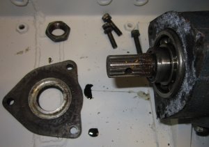
I decided I’d try Plan A. Since both Plan A and B required a chain drive on the front input, I decided to work on that first. There was a cover on the front input shaft that held the rear bearing on the pinion shaft in place. The cover was held in place by 3 bolts that could be used to hold an adapter in place.
It was going to require some careful machining to replace this cover since it had to hold the bearing in position and contain a seal.
I made a plastic mock up of the adapter plate that would be required.
It was difficult to tell exactly, but it looked like it was going to require a 4 inch center distance for the drive line to clear the clutch. The problem is that the clutch location is adjustable up and down to allow for tightening the belts. I placed the clutch in the center of its adjustment. I used the plastic template to make a wooden adapter plate that would hold everything in better alignment.

The round wooden disks are to simulate the chain sprockets that I planned to use. I also made wooden mockups of the flange bearings I planned to use to make sure there would be clearance for them.
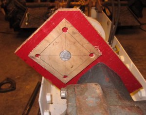
Additionally, I used an extend shaft to make sure there would be clearance if I later decided to shorten the Original’s frame to its original length.
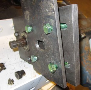
When I was satisfied that everything would work, I paid a visit to my friend, Chuck, and he machined the more critical parts of the front adapter plate for me. We made the adapter plate out of ½” by 5” CR.
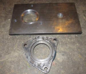
In the picture you can see the adapter plate and the cover plate it replaces. I used my CNC mill to machine slots in the adapter plate to allow for adjustment of the chain tension.
If you look closely, you can see that the center hole for the ¾” shaft looks a little strange. That is because I had Chuck to machine a ¾” hole in line with the mounting hole that he’d machined. I later decided that hole should be in the center of the 5” wide plate to center the drive sprocket. So I moved the hole over when I machined the slot on my mill. It’s just a clearance hole so it only hurt the looks.
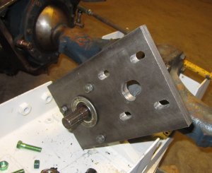
I had hoped to use a flange bearing on both sides of the adapter plate to hold the ¾” drive shaft. But it quickly became obvious that the flange bearings were too thick for that. So I machined another plate that could be offset from the adapter plate to hold a second flange bearing. Although I didn’t like the looks of that setup as well, it was a better setup because the sprocket wouldn’t be cantilevered on the drive shaft.
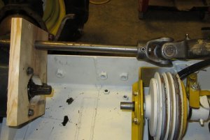
Obviously in this picture the second plate still has to be cut to the correct length and secured in place. With this plate made, I used all thread to again make sure there would be clearance for a shortened frame if I later decided to do that.

It looked like there would be plenty of clearance. However, if the clutch was in its lowest position and the chain drive in its shortest position, there would be some interference.
With the front end in good shape, I turned my attention to the rear end. And, that’s when I encountered problems with Plan A. Again I started with a wooden mockup.
The wooden mockup indicated that the driveline would have to be at least 3 ½” below the center line of the PTO shaft to clear the frame and clutch of the Original. That meant that the smallest combination of pitch diameters for the gears would have to be 3 ½”. That is, if both gears had 3 ½” pitch diameters, I would have a center distance of 3 ½”. If I made the driven gear smaller then 3 ½” (which I needed to do to speed up the drive shaft) the driver would have to be larger then 3 ½”. But, with the limited space available, I wasn’t even sure there was room for a 3 ½” gear, let alone a gear box. And, using two 3 ½” gears on the rear would require that all the speed increase would occur at the front end. That would require one extremely large sprocket and there wasn’t room for that.
So, I came up with a Plan C. I decided I’d use a chain drive at the front and rear to get the speed increase that I needed and use a 1:1 gear box under the frame to reverse the direction of the driveshaft. And, as a fall back position, I could also drop back to Plan B – a chain drive at the front and rear, reverse the engine and flip the rear ring gear.
Using the wooden mockup as a guide, I machined an adapter for the rear PTO. The rear PTO had a cover held in place by two 8 mm bolts that I used to hold the rear chain adapter.

When I mounted the rear bracket it was obvious I had no adjustment in the flange bearing. At the very end of the adjustment slot, it was bottomed out on the PTO adapter.
The mill made short work of the problem.
With both the front and rear brackets made, I decided I’d better flip the frame back over to make sure there were no surprises. When I originally flipped the frame upside down, I did it by unbolting the rear end, rotating the frame around the front wheels, rotating the rear end around and bolting everything back together. To put it back upright, I decided to unbolt the front end and flip the frame around the rear end. (That turned out to be much harder then I thought it would be but felt it was a better method.)
When I got everything removed to upright the frame, I decided it was as good a time as any to shorten the frame if I was going to do it. Besides, I was getting tired of continually checking to make sure everything I was doing would work on a shortened frame. I marked the section I wanted to remove, got out my trusty angle grinder and cutoff wheel and cut the section out.
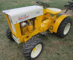
When I got the frame welded back together, I couldn’t wait until later to see what it would look like. So while I had it right side up I reassembled the entire tractor.
I really prefer the original frame length and was happy with the result.
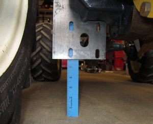
Everything looked like it would work, but I wanted to check ground clearances while I had the tractor right side up. When I measured the height of the rear end on the Original, it measured about 6 inches of ground clearance. The rear bracket that I had mounted had a little over 5 ½” of ground clearance.
The front bracket left about 4 ½” of ground clearance, but I will gain at least a half inch by cutting off the lower corner of the bracket. That will still result in less ground clearance then I’d prefer, but I can live with it.
Having checked everything, I again disassembled the tractor and flipped it back upside down.
Like the front end, the rear end was going to require a second plate to hold a second flange bearing.

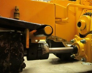
In the picture, I’ve already tack welded the second plate in position. I had to machine some clearance in the end of the bracket to allow the large sprocket to be mounted on the PTO shaft after the bracket was mounted.

The sprocket on the PTO shaft was mounted using a 1 ½” I.D. sprocket that slid over a 1 ½” O.D. adapter that fit the PTO spline shaft.
 You can also observe in the picture that two of the socket head screws had to be replaced with standard Grade 5 bolts to allow room for mounting the adapter plate. Everything was a close fit on the rear bracket.
I welded the second plate in position for the front bracket.
It was a close fit between the end of the clutch shaft and the front input shaft, but there was a good quarter inch of clearance although it doesn’t look like it in the picture. I could always saw some off the end off of the front input shaft if it became necessary.

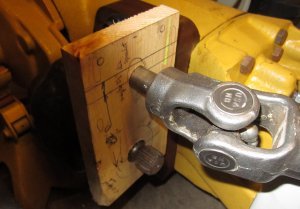
With the front and rear adapters completed and tacked together, I looked at what it would take to make the 1:1 gearbox. I made a wooden mockup of the approximate size and shape of the gearbox.
With the mockup, it looked like the gearbox would have to connect directly to the rear adapter. Although the driveshaft had more of an angle then I would like, it looked like it would work. But it soon became obvious that the gearbox would have to be mounted much further forward then shown in the picture above. Even with the flange bearings in their lowest position the drive shaft angled up to the gearbox.
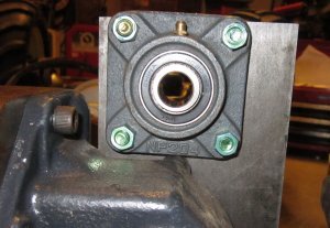
While I was trying to decide how I was going to make a gearbox (and if I’d rather drop back to Plan B), I happened upon a 1:1 gearbox. While this gearbox wasn’t heavy enough to handle the loads that would be encountered on a 4 X 4, it could be used for a “proof of concept.” I used a shaft to align the gearbox with the output of the chain drive and made an adapter to hold it in place.

Since I didn’t have the front end installed on the tractor, I decided that I’d flip it back upright and install the front end before measuring the length of PTO shaft needed to complete the driveline. I decided I’d paint the underside of the tractor while it was upside down. I had used up all my LoveJoy couplings so I had to order another one for the connection between the gearbox and rear chain drive so I couldn’t yet complete that connection.
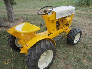
I again reassembled everything when I got it flipped upright. I still had a lot of painting to do, but it was getting closer to being done.
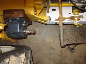
The gearbox looks really low in the picture, but I only loose about three quarters of an inch of ground clearance compared to the original rear end.
The drive from the rear chain drive to the gearbox was completed, but I still had to remove the support bracket for the rear chain drive, round the top and make a shield.
I lost about an inch of ground clearance with the front chain drive. I still had to make an adapter to use to shorten the PTO shaft with U-joints before I could complete the connection from the front chain drive to the gearbox.
The whole drive system turned out to be a little “bulkier” then I had originally planned, but other than that, everything turned out OK. Recall that I stated earlier that the gearbox I installed is not “stout” enough and will have to be replaced. The gearbox I used is just for a proof of concept.
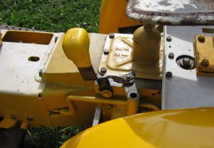
One other thing that I haven’t mentioned is the engagement lever to engage the rear PTO. It’s amazing how much time can be used on what turns out to be a really simple solution. I spent a good half day just deciding how and where to put the engagement lever.
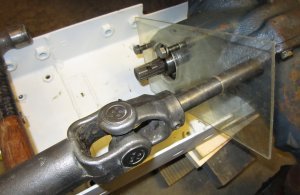
With everything assembled, I measured the length required for the front drive shaft. Rick had furnished me with a PTO shaft from a snowblower that I planned to use. When I measured, I found the drive shaft would have to be a lot shorter. I cut off the splined end and took it to a friend who made me an adapter to fit the splined section tightly in the end. I used a spiral pin to hole it in place.
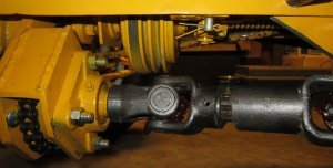
The rear section of the snowblower drive shaft had to be shortened as well.
I removed the rear chain drive unit and rounded off the top on a CNC mill. I eventually plan to form a guard to cover this entire unit.

Also, eventually, I think the Love Joy coupling on the rear drive shaft will require a couple universal joints to replace it. But, for now, what I have works for the proof of concept gearbox.
I managed to get everything painted an put back together to get some pictues.

And that’s it. I installed the two roller chains and tried it out. Everything seems to work as it should. I’m hoping to get a plow mounted on the tractor and try that out. When that happens, I’ll make a video and post it here.
As usual, I hope you find this article interesting and useful. If you have any comments or questions please feel free to contact me through this website.
