Note: This is one of those articles I’ve been working on as time permits. I finally decided to go ahead and put it on my website even though it isn’t finished so you’ll notice it drops off kind of suddenly at the end. I’ll add to it as time permits. And, I should add, the Mini 560 was one of the easiest projects that I’ve done.
Note about Note: I think I’ve finally completed the article. I’m sure I’ll do some adding, subtracting and editing over time, but all the main points are completed. I hope you enjoy it as much as I enjoyed the project.
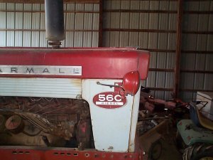
For several years I had displayed several Cub Cadets that I had refurbished at a local Antique Iron Show and was looking for something a little more unique to display. On a Cub Cadet forum in 2000 I saw a Mini 560 that someone had made. That’s what gave me the idea of building my first Mini tractor. I wish I had recorded the person’s name so I could give him credit, but I have no way of recalling that information.
The gentleman that had built the Mini 560 didn’t seem to want to give out much information about its construction. But that was ok with me, since I wanted the challenge. It was indicated on the forum that he used 18” rear tires which was a big help.
My uncle farmed with a 560 so I paid him a visit and took some pictures and measurements.

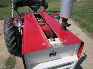
My uncle did indicate to me that he’d moved the headlights to the front so he wasn’t bothered by bugs attracted to the light when working after dark.
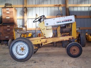
I had purchased 4 Cub Cadets from an individual, and he threw in a partial roller. It had the front and rear wheels, clutch and steering wheel, but didn’t have a grill, grill housing or hood. It had set outside for quite a while and was a little rusty, but nothing serious. The frame also had a couple extra pieces of flat iron welded to each side of the frame at the front which would add extra strength.
The deal had also included a 10 hp Kolher engine off a Model 155 Case garden tractor that was in really good condition. The Case has a much shorter crankshaft then a Cub Cadet on the PTO end so I hadn’t been able to use it on any of my Cub Cadets. It was a great candidate for the 560 since the 560 wouldn’t include a front PTO.
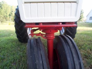
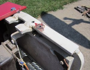
Since I thought the rear would be pretty easy to fabricate, I started with the front end. I started by cutting a piece of 3/8 by 6″ steel the width of the frame. The frame is 10 ½ inches wide so I made the 3/8” piece 10 ¼” long so it would fit nicely under the frame. I c-clamped it under the front of the frame (flush with the front) and marked the holes that were used to originally mount the grill housing on the Cub Cadet. I removed the piece of steel and drilled the holes. I also located the center between the drilled holes and used my mill to mill a 1 ½” diameter clearance hole for the front spindle. I had calculated that a 1” diameter round would be large enough for the front spindle, but it just looked too small. I decided a 1 ¼” shaft would look better. I decided to use a 1 ¼” bore ball bearing to support the 1 ¼” diameter shaft. Obviously there is some thrust on this bearing due to the weight of the tractor and engine, but I felt this oversized bearing would handle the side thrust. I placed the 1 ¼” four bolt flange bearing centered over the hole and marked the location of the four bolt holes that hold the flange bearing in place. I then drilled the four holes.
I made my own channel section and welded it to the top of the 3/8 by 6” piece directly above the 1 ½” diameter hole.

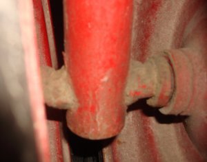
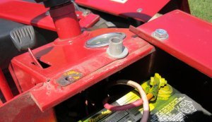
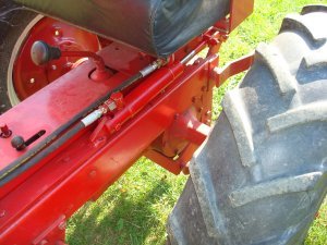
The channel section was made up of ¼ by 1” pieces for the sides and a ¼” by 2” section for the top. I drilled two holes and mounted a 2 bolt 1” bore flange bearing to the top of the channel. The front vertical spindle is made of 1 ¼” round. I turned a section of the top of the round down to 1”. The very end of the shaft was turned down and threaded for a ¾-16 nut. The 1 ¼” portion of the shaft extends up through the bottom bearing and the 1” diameter section extends through the top bearing. The shaft is prevented from falling downward by the ¾” nut and a washer. Note that you can also see the shorter crankshaft in the above picture. I slid a heavy washer with a 1 1/4” bore and an extension for the drag link that I’d made up to the bottom bearing and welded it in place to prevent the shaft from moving upward.
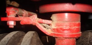
In the picture you’ll notice that the drag link extension is bent upward and there’s an extension welded on it. You might also notice in the picture that there are some spacers above the washer I’d welded in place. I had to use the spacers to level the tractor once I installed the rear wheels and the drag link extension had to be bent up to clear the front wheel. I also added a small reinforcement between the extension and the added washers for additional support.
With the vertical spindle section of the spindle completed, I worked on the axles to hold the front wheels. I drilled a ¾” hole through the bottom of the 1 ¼” round and stuck a piece of ¾” round through the drilled hole and welded it in place. On each side I heated the ¾” round and bent it slightly downward. (It helps to partially cut the round on the “compression” side where you want to make the bend and then weld the cut when you’re finished.) I wish I could give you an exact angle to bend the two sides downward, but I just bent them until it looked right to give me the camber that I wanted. I slid the two front wheels on the each side to determine how close together I wanted them. I welded a washer as a stop on each inside and cut the remaining shaft to the width of the wheel, drilled and taped each end for a 3/8” bolt and put the wheels on to finish the front end.
In one of those senior moments, I extended the piece where the drag link connects out to the left. (In the picture above, it extends out to the right.) When I made a drag link and connected the front spindle to the steering gear box on the Cub Cadet, I had a major problem. When I turned the steering wheel to the right, the tractor steered to the left and vice versa. It was a simple matter to rotate everything 180 degrees, but it sure made me feel stupid.
With the front end in place I installed the engine and drove the tractor around to check out the front steering.
It wasn’t the best driving conditions, but it sure was interesting.
With the front end completed at least temporarily, I turned my attention to the rear end. I had located some 18” rims with implement tires that I could use until I found some ag tires. The inside hub that bolts to the original Cub Cadet axle is 5.375 inch diameter with 5 equally spaced holes located on a 4.5 inch diameter. The outside hub is 7.0 inches in diameter with 6 holes located on a 6 inch diameter. Both hubs were milled from 3/8 inch flat plate. The inner hole for each hub has a 1.9 inch diameter that fit over a piece of thick wall tubing that I had on hand. The hubs were all cut on a CNC milling machine.
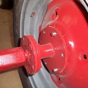
I pressed the hubs over a 6 inch long piece of the thick wall tubing. I took three 3/8″ coupler nuts and screwed bolts in until their length was the correct inside dimension for the spacing between the two hubs. I used a nut to lock them at the correct length. The three coupler nuts and attached bolts were spaced equally around the hubs and a C-clamp was used to pull the hubs in tight against them. (Unfortunately, I didn’t take any pictures of the assembly before welding.) That assured that the two hubs were parallel. The center tube was then welded to each hub. After the hubs were welded, I tapped the holes. The inner hub just had to have clearance for a 3/8″ bolt; the bolts just go through the hub and screw into the original cub cadet hub. The outer hub had to be tapped for a ½-20 NF thread. The hubs and wheels were installed on the tractor. The tractor was now completely on its own wheels!!!
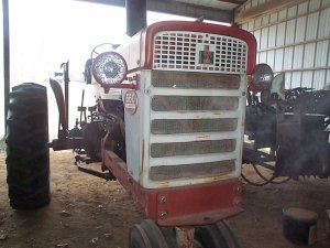
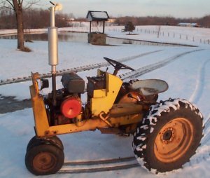
After a lot of searching I located some used 7.50-18 ag tires from a combine salvage dealer. The fellow I bought them from said they came off a corn planter. After installing the tires and reinstalling the engine, I could drive the tractor around. That’s when I found that I had to add the spacer discussed above to “level” the tractor. (With the tractor level, the front spindle was 10 ½” from the bottom of the tractor frame to the centerline of the ¾” axles.) By this time, it was winter as can be seen in the photo below. But the tractor was fun to drive around even if it was cold outside!!!
All the running gear was completed and it was time to work on the sheet metal. Since the Model 100 I started with didn’t have a hood, I decided to make my own hood. Besides, I wanted the look of the 560 where the hood extends forward of the grill and I couldn’t get that using a Model 100 hood.
I decided to make the red section of the hood in 3 pieces. The height of each side of the hood would be critical but the width of the top part wouldn’t be critical since it would be covered by a center cap. In other words I could make the two side sections and then just cap them with the center section.
I made all the hood sections out of 16 gage steel. Eighteen gage would have been much easier to work with but I felt the extra strength was worth the extra trouble. I had two sophomore students looking for a project, so I assigned them the project of designing and building a roll bender that would bend 16 gage steel with a 2 inch diameter. For the side sections I started with two 16 by 29 ¼” sections of 16 gage steel. I placed a bend in each section, trimmed it so the horizontal section was approximately 6 ¾” wide (measured from the outside) and the vertical section was approximately 7 ¾” sections high (measured from the top). The widths didn’t have to be exact since I used a brake to bend a flange so that each section was the correct length. The top horizontal section was 6 ½” wide and the vertical section was 7 ½” high after I bent the approximate ½” flange.
It’s difficult to see in the left picture above, but there’s a 1/2″ flange the runs the full length on each side of the hood section. As I discussed previously, the width of the top section after the bend wasn’t critical since it would be covered by the center cap. On the other hand, the height of the side section after bending a flange was critical since it would all show. The main thing was it had to be a consistent height or it would look uneven.
I welded a section of ¼” by 1” flat across the top and side of the rear pedestal. I drilled and tapped ¼-20 holes in each of the sections to attach the hood sections.

Likewise I welded a 1” by ¼” flat across the top of the front pedestal to attach the front of the hood sections. Again, holes were drilled and tapped in this section. I used the hole where the hinge originally pivoted on the Model 100 as an additional support hole. This support required that I place a nut on the inside, but it was in an easy location to reach through the center opening between the two hood sections.
You can notice in all the previous pictures that the paint is “peeled” from around the mounting holes. That’s because I got in too big of a hurry to mount the hood sections after painting and didn’t allow enough drying time. I’m always too anxious to see what the finished project is going to look like.
With the two side sections installed, it was easy to make the center cap. I made a 5 ¼” X 29 ¼” section and bent a ½” flange on each side. (The final cap was 4 ¼” wide after the flanges were bent.)

The “end cap” for the center section was simply a piece that I bent and used JB weld to attach. Since I had already welded in the sections to be used for mounting the center section, I just had to drill and tap some additional holes. Notice that the rear section required a spacer to get the correct height.
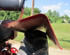
With the red section of the hood completed, I worked on the side skirts. With the experience on the top section it was easy to make the skirts. The long section of the skirt was made by bending 3/8” inch flanges on each side of a 3” wide by 29 ¼” long section of 16 gage steel. The section was 2 ¼” wide after the flanges were bent.

Notice the notch in the flange at the rear where the skirt is bolted to the mounting bracket. Likewise the flanges had to be cut off the front section so it would fit flat against the grill.

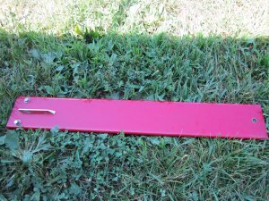
The front bottom section of the grill was simply a piece of 16 gage trimmed to size and an arc cut out using a saber saw and bolted in position.
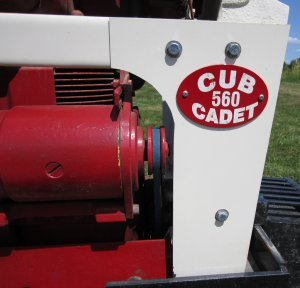
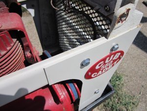
Notice in the above picture that the decal is held in place by two screws. I always place the decals on a piece of aluminum and mount the aluminum section using screws. Later, if I need to repaint a section, I can easily remove the decal section using the screws.
With the hood completed, I turned my attention to the front grill. I originally intended to simply weld five lengths of 1” by 1” tubing across the front of the grill. But, since I really only like to weld as a last resort, I bolted two sections of 1/8” by 1 ½” flat along each side of the grill and welded the four sections of 1” by 1” tubing to these pieces.
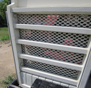
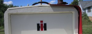
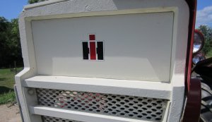
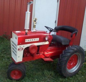
I tried to find a grill section that looked like the 560 for the top section but wasn’t successful. So I simply painted the insert and placed an IH logo on it.
With the Mini-560 “finished”, I showed it at several local antique iron shows. As a matter of fact, I won a trophy for best of show the first time I displayed it.
I decided I wanted to make an implement to attach to the Mini-560 for future shows. I felt that a pull type sickle bar mower would be appropriate for the years the 560 was sold.
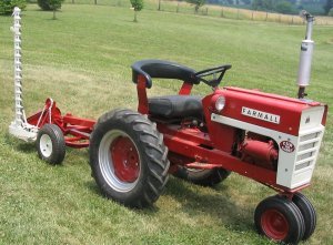
But the pull type mower was very cumbersome to load and unload for shows. Even with weight added to the tongue of the mower, it tended to be unbalanced over the wheels. So I decided that I’d add a 3-point hitch and build a mower that would be mounted. The 3-point mower would also be appropriate for the 560 era.
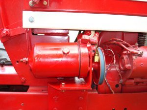
I started by mounting a hydraulic pump/valve combination that was used on early gear drive Cub Cadets. I had one that I’d acquired that didn’t have the mounting bracket, control lever and hydraulic cylinder. Also, the addition of the hydraulic pump added to the “wide look” that the 560 has.
You can see in the above picture that the mount was a large section of angle. The section of angle that bolts to the tractor frame has slots where the pump attaches to allow for belt tensioning. The picture also shows the control linkage. With the pump mounted, I started working on the 3-point hitch.
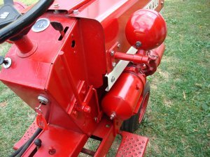
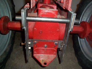
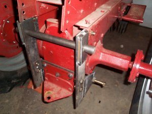
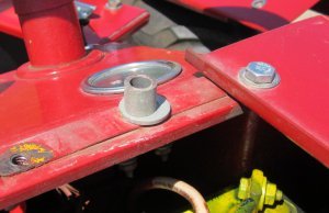
The main frame of the 3-point is bolted to the frame of the tractor at the top and the original 2-point portion of a Cub Cadet 3-point hitch. Deciding how to mount the main frame of the 3-point was the difficult part of the project. Once the main frame was in place, it was just a matter of making all the lift arms. Notice that I extended each side of the frame forward for a connection for the two lift arms. This allowed me to use longer lift arms and let the arms swing in a larger arc.
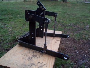
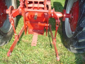
You can see in the picture above that the entire 3-point can be removed by removing 4 bolts on each side. There are two bolts on each side that attach the 3-point to the frame of the tractor and 2 bolts on each side that attach it to the original cub cadet 3-point bracket. Once this “main frame” was built, it was an easy matter to add lift arms and bend them so that they were centered over the two 3-point arms. The third link attaches to a bracket welded to the seat mount.
It took a couple tries, but I finally got the hydraulic cylinder mounted so it worked like I wanted it to.
With the hydraulic system completed, I could make a mounted sickle bar mower. I wanted it to emulate an International mower as closely as possibly. I had the remnants of a Haban mower that could be used for the drive and bar section of the mower. The problem was getting the mower to “float” and lift properly. Haban sickle bar mowers have a very unique way of accomplishing that. With the Haban setup and the limited space available to work in, I couldn’t figure out a way to set it up like an International. I finally relented and stuck with the original design that Haban used for getting the sickle bar to float and lift.
I did want the large “arc” that is representative of an International mower. I tried without success to bend a section of pipe. With the limited metal working tools I have available to me, that wasn’t possible.
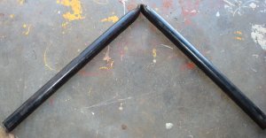

When I looked around I found an old bed frame that I could make use of. I cut off both ends of the bed frame and welded them together to get the arc I wanted.

With that final decision, it was a simple matter to weld up a frame to attach the Haban mechanism. It’s difficult to tell in the picture, but I welded part of the original Haban mower to the frame that I built. Ordinarily I wouldn’t have made that a welded connection and destroyed the integrity of the Haban mower. But I had to cut and grind several large sections of metal off the Haban mount that a previous owner had added. I had removed so much extra steel and weld that I felt that I had improved the integrity even with the welding I did to it.


The only problem now was that I was afraid the front end might be too light when I was loading and unloading the tractor on my trailer. So I purchased some suitcase weights online and made a front mounting bracket.

And that’s it. I will say again that the Mini-560 was the easiest “mini” project I’ve undertaken with the exception of the 3-point hitch. It did take some “head scratching” to figure that out.
And, here’s a couple pictures of the finished project.
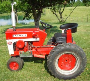
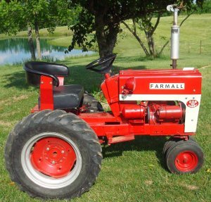
As always, I hope you find this article useful. If you have any questions or comments, feel free to contact me through this website.
