Building the Mini Cub
Before I started building the cub, I experimented with different setups in an attempt to get some ideas of the general size of the tractor and wheels.
The mock ups indicated that I needed a wheel and tire in the 15” range. It took two years of looking for the “deal” that I wanted, but I finally located the rear wheels to use at a flea market. With the purchase of the rear wheels, I could get a much better mockup of what I wanted.

With a good idea of the proportions I wanted, I started by making the rear end. I wanted it to be close to the same width as a normal narrow frame cub cadet for hauling purposes. Basically I shortened the left hand side housing as much as practical and adjusted the right side to give me the correct width. I cut a 2” section from the left axle housing and welded the housing back together. Two inches doesn’t seem like much, but with the offset in the rim, it was a nice fit.

It was kind of a crude way of doing it, but I reinserted the axle and used it to align the two pieces before welding. The housing must be some sort of cast steel because it welded reasonably easily.
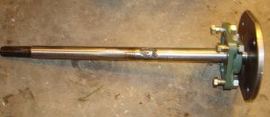
Next the axle had to be shortened to fit the housing. After shortening the axle, I cut the hubs on my CNC mill. Since my mill didn’t quite have the travel I needed in the y-direction, I just left two flat spots on the outer radius of the hub. That worked well because I only had a 6 inch width section of metal to use. The hubs are 3/8” thick.

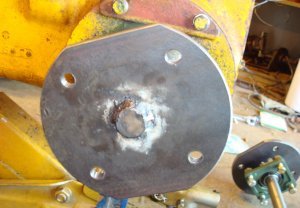
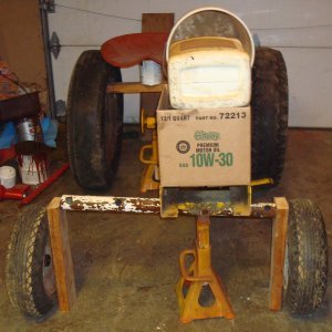
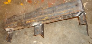
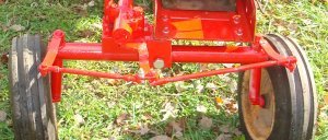
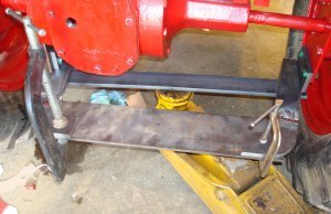
I then made the right hand side so it would have the wheel base that I wanted (36” outside to outisde). I was afraid that if I just extended the cub cadet axle housing it wouldn’t be strong enough to support the weight. So I bolted a 3 inch channel across the top of the cub cadet frame and let it extend outward to support the right axle bearing. To attach the channel to the frame I bolted a piece of two inch angle on both sides of the frame. I welded the channel to the two pieces of angle. Since the two pieces of angle were bolted to the frame, the whole channel support could be removed whenever I wanted. I extended a 4 inch long section of the channel downward at the outer end and bolted a 7” long piece of ¼ by 4 inch flat to it. (The extra length is for connecting a drawbar.) The 4” flat had a clearance hole for the 1” axle as well as 4 holes to attach a 1 inch bore flange bearing. I bolted a 1 inch bore flange bearing to the flat to support the axle.
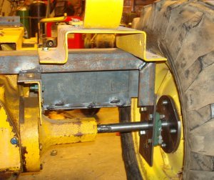
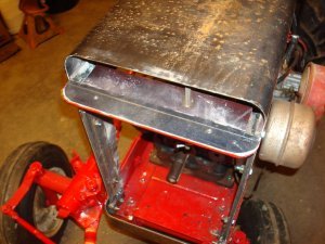
I increased the length of the axle using the method described in the Tips and Tools section of this website. Again, it was a crude method, but I inserted the extended axle in the cub cadet housing and used that as a means of aligning the outer bearing. Notice the picture above was taken “after the fact” and includes the foot rest support and a temporary seat in addition to the axle support.
With the rear end done, I could get my measurements for the front end. I played around with different size tubing to find an outside diameter that I felt looked right with an appropriate size for the spindle tubes (housing). I settled on a 2” black iron pipe. Getting the correct length for everything was really tricky. The spindle tubes angle outward and the spindles themselves had to add toe-in to the front wheels. I made several mock ups until I was satisfied that I had the correct lengths. I didn’t take any pictures of that process, but I had tubing supported with jacks and wheels leaning against 2 by 4’s!!!
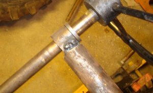
As stated previously, the cross tube was made of 2” black iron pipe. The spindle tubes were made of 1 inch I. D. tubing with a 1/8” wall. That meant the holes in the cross tube had to be 1 ¼” and allow for the spindle tubes to angle outward. After several days of thought I came up with a method for doing this that I felt would work. I used the method under Tools and Tips to drill a ¾” hole in the center of the cross tube through both sides. I placed a ¾” shaft through the drilled hole in the cross tube and sat the whole thing on the mill. I made sure the ¾” shaft was parallel to the mill table and secured a piece of angle iron to the mill table to use as a stop for the end of the cross tube. I had calculated that if I milled a 1 3/8” hole in each side of the cross tube the resulting clearance when I inserted the 1 ¼” O.D. tubing would give me the angle I wanted on the spindle tubes. In other words there would be enough clearance in the milled holes that if the spindle tube was against the inside edge of the 1 3/8” hole at the top and the outside edge at the bottom it would have the correct angle.
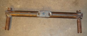
I milled the 1 3/8” hole in the top of the cross tube, flipped it over, placed it against the stop, made sure the ¾” shaft was horizontal to the mill table and milled the second hole. Then, flipping the cross tube end to end and doing the same thing on the opposite end gave me the holes that I needed.
I tried to come up with some “precision” way of holding the spindle tubes in position as I welded them, but couldn’t get anything to work. I ended up supporting the outer ends of the spindle tubes at the same height above the floor, used my feet to hold them at the outward angle and welded them in place. When I finished, all the measurements I made indicated they were consistent and at the same angle. It never hurts to be lucky. As you can see in the above photo, I also welded a ¼” thick plate to each side of the axle tube in the center to give me more bearing surface at the central pivot point.
Next the axle housing had to be connected to the front of the cub cadet. Measurements showed that the center of the axle had to be directly below the outer edge of the frame on the right side to be centered with the rear end of the tractor. I bolted a 10 ½” long piece of ¼” by 4” flat under the front frame flush with both outer sides of the cub cadet frame. (Later I had to extend a ¼” by 2” piece of flat out the right side for a place to attach the steering gear.) I would have liked to have the steering gear centered over the axle housing, but the distances just couldn’t be worked out.

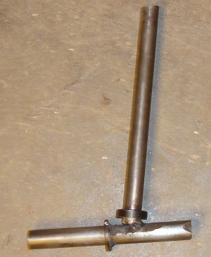
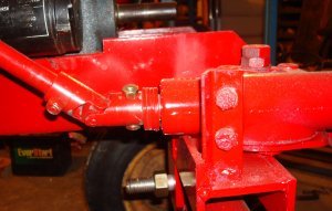
As stated previously, I welded a piece of ¼” flat to both sides of the axle housing where I’d drilled the ¾” hole to give a larger bearing surface. I welded two pieces of 3/8” by 2” flat to the ¼” flat directly below the right side of the cub cadet frame and drilled a ¾” hole through them. The 3/8” pieces were far enough apart to allow the axle housing to fit between them with enough clearance for a flat washer. Notice in the right picture above I used ¾” all thread to hold the pieces in alignment as I welded them. The axle housing with attached spindle housings could now be connected to the front of the tractor.


I had left the spindle tubes “plenty long” even though I had some rough idea of how long they should be. With the axle housing attached to the front of the tractor I could check my measurements and cut the spindle tubes to the length required to get the tractor level from front to rear. I inserted a flanged sleeve bearing in the top and bottom ends of the spindle tube and placed a length of ¾” cold rolled shaft through the bearings. I placed an additional piece of ¾” shaft that would make up the axle across the bottom and determined the angle I wanted to get some camber on the wheel when it was attached. I used a piece of cardboard to mark the angle that I wanted. I then removed the piece of ¾” shaft from the spindle tube and c-clamped everything to a piece of flat steel to hold it in position for welding. (That required a lot of time, patience and redoing to get it where I wanted it.) I left both pieces of the ¾” shaft long enough that they could be trimmed to the length I wanted after they were welded. Once one spindle was made it was fairly simple to duplicate it for the other side.

The horizontal portion of the spindle was cut to the correct length to accept a cub cadet wheel. Then a hole was drilled and tapped in the end for a 3/8” bolt that would secure the wheel in place. Also, you can see in the picture that thick ¾” washers were added to the spindle to act as bearing surfaces.

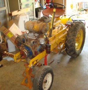
With the front wheels mounted I turned my attention to the steering. As I stated previously, it wasn’t possible to mount the steering gear at the center of the tractor. I welded a piece of 1” by 1” angle to the front axle support and bolted the steering gear in place.

I also temporarily added drag lengths to the top of each steering spindle. Luckily they fit tight enough that they wouldn’t rotate freely, and I could make some necessary measurements.

It very quickly became obvious that the lever in the gear box was not at the correct angle and did not have sufficient travel to properly steer the tractor. So I welded an extension at the angle and length that I felt was needed.

I experimented with the extension until the length was what was required and welded a piece across the end to attach the tie rods.
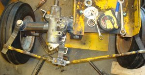
With everything in place and working properly, I could cut off all the extra lengths and round all the corners to improve the looks of the whole thing. Notice in the picture above that the drag links are still not bolted to the axle spindles. That was one of the final things that I did. Unfortunately the only picture I have of that is after I had assembled and painted everything.
With the gearbox in position and working, I could determine the location of the steering wheel. Up until this point I had waited on mounting the steering wheel because I wanted the steering shaft to run back parallel to the tractor frame and needed to know the position of the gearbox before mounting the steering wheel support.
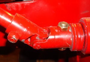
On a Cub Cadet the steering tube adds support to the steering shaft. Since I wasn’t using that tube, I needed to add extra support to the steering shaft where it came out of the steering gearbox. I found a ball bearing with a ¾” bore that had an O. D. that just fit inside the opening in the gearbox. I cut the steering shaft off to the correct length and added a universal joint between the gearbox and the steering shaft that held the steering wheel. I placed spacers between the universal joint and the bearing that I’d added to hold the bearing in the gearbox.
I mounted a temporary seat on the tractor so I could get the correct height of the steering wheel. I bent a piece of 1 ¼” O. D. tubing at a 90 degree angle to support the steering shaft at the upper end. Again, I didn’t get a picture of this before it was painted.
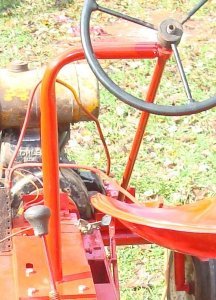
The “purist” among us will notice that the steering wheel support has a much sharper radius then on an actual Cub. It’s that way because it was the only method I had for bending the tube. But, as luck would have it, the sharper bend permits more “knee clearance” and permitted the steering wheel to be mounted lower then if it had a larger radius. To mount the support, I machined a 1 ¼” hole in a piece of 3/8” flat, inserted the support in it and welded it in place. The flat was then bolted to the cub cadet frame. That’s overkill I know but I had used a smaller support on the Mini-H, and I never liked the feel of it. It just didn’t feel as “rigid” as I felt it should be.
As much as I tried, I couldn’t get everything held in position at the same time to cut the exact lengths that I wanted as I was mounting the steering support. So, before I cut off the steering support at the top, I had made an adjustable piece to support the steering shaft at the end of the steering support. I welded a piece of the 1” I.D. tubing to the end of a piece of 1” O. D. shaft and inserted a ¾” bore sleeve bearing in the tubing. Remember that I made the steering support of 1” I. D. tubing so that the 1” shafting easily slid in the end of it.

By being able to slide the piece in and out of the steering support, it made it much easier to determine where to mount the steering support and how tall and long to make it. After the steering support was bolted in place, I cut off the top section to the correct length, slid the 1” shafting into the tube and welded it in place.
And, that’s the one thing I know I’d definitely do differently. I don’t know why I welded it in place — in too big of a hurry I guess. I generally prefer using bolts where ever I can. And, this would have been a great place to bolt it in position in case I ever wanted to remove it or redo something. This would also be a good place to mention that I used the method described in the “Tools and Tips” section to lengthen the steering shaft.
The clutch/brake pedal on a Cub Cadet is on the left hand side. Obviously this setup wouldn’t work on the Mini-Cub. I removed the roll pins that held the clutch pedal in place and removed it (with some difficulty) from the frame. Rather then make a new pedal, I modified the one I removed. The clutch arm wasn’t symmetrical on the shaft so it had to be lined up and new holes drilled. (I used the method in Tips and Tools to center the hole.) If you look closely you can see the original hole on top of the shaft just to the right of the clutch arm.
When the shaft was inserted from the right hand side the “foot rest” was upside down and backward. I cut the pedal in two places and welded it back together. One cut was to make the end of the pedal turn upward, and the second cut extended the foot pedal outward.
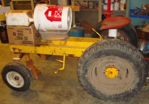
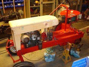
At this point I stopped working on the actual tractor and worked on an engine. I had a 7 hp engine that I wanted to use, but it smoked too much. And, since I was going to overhaul it anyway, I decided to also replace the starter/generator with an internal charging system and a 7 horsepower starter I had obtained. When I built the Mini-H I originally left the starter/generator in place. But the starter/generator made the tractor look too wide. Since the Mini-Cub also needed a long narrow look, I decided to replace the starter/generator at the beginning of the process. I overhauled the engine, replaced the starter/generator with a starter and placed the engine in the Mini-Cub.
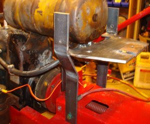
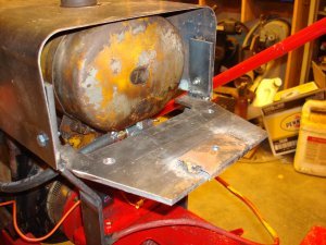
I was anxious to drive it, but it needed a gas tank. I was tempted to just mount the gas tank temporarily so I could drive the tractor. But my experience with the Mini-H and Mini-560 had taught me that finding a place for the gas tank after all the sheet metal work was finished could be a real challenge. I made some rough measurements and mounted the gas tank where I felt it wouldn’t be in the way of the sheet metal. I c-clamped the mounting brackets in place so final adjustments could be made after I mounted the sheet metal for the hood.
With the engine overhauled and in place and the gas tank mounted, I could drive the Mini-Cub. I was pleasantly surprised at how easily it steered.
With all the “mechanical stuff” completed and the tractor being able to be driven, I turned my attention to the sheet metal – the part of these projects that I don’t really care for. But it has to be done. I made a wooden mock up of what I wanted the hood to look like.
After assembling the wooden hood I decided that it didn’t have the long, extended look of a Cub. I added a 3 inch wooden extension to determine if that would improve the look.
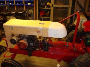
In the picture above you can see a “slot” in the middle of the wooden hood. That slot is directly above the gas tank cap. You can also see the 3 inch extension and the wooden pattern for the “gas tank”. The white is plaster.
I wanted the long “straight” section of the hood to be made out of sheet metal. The rounded front and back sections had to be made out of fiberglass. When I measured everything I found that the metal center section could be 2 feet long. I sheared off a 2 foot section of 16 gage sheet metal and used it to form the center section. There’s a complete description of this process under the “Roll Bender” section in the “Tips and Tools” article of this web domain.
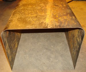
I left extra length on the sides of the hood and trimmed them after completing the gas tank.
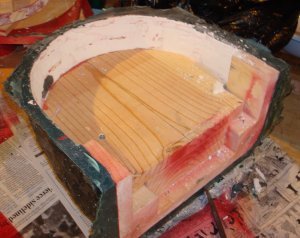
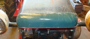
The “gas tank” probably requires a little more discussion. I placed gas tank in quotes because on the finished cub, this section is a gas tank in name only. The wooden pattern is used to make a fiberglass shell. The actual gas tank sets in front of this shell. I used the same procedure to make the gas tank as I used on the Mini-H. Well, almost the same. It had been long enough that I’d forgotten a lot of the stuff and did most everything wrong. But, I’ll discuss those mistakes later. The gas tank on an H has more of an elliptical shape. The gas tank on a cub appeared to me to have more of a circular shape. I wanted the hood to be 10 inches wide. So I cut several 10 inch diameter semicircular wooden sections on a bandsaw. I had calculated how much shorter each section would need to be so that they would have a semicircular cross section when they were fastened together. After I had all the sections made and screwed together I used a belt sander to round off the edges. I then used plaster to get the final shape I wanted. Unfortunately I didn’t take a lot of pictures of this procedure.
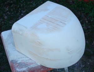
The picture above is a picture I took sort of at the midway point. There is a picture later of when I took it all apart to remove it from the fiberglass mold. There was one thing I did do really right. When I’d made the pattern for the Mini-H, I’d glued all the boards together. For the Mini-Cub I used screws and worked from the top board down. That way I could take out the screws and remove the individual boards to get the pattern out of the mold.
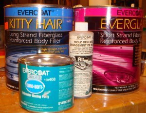
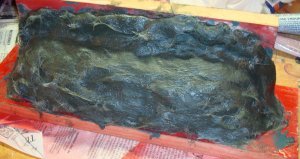
With the pattern completed, I purchased some wax and hair spray so the pattern could be removed from the mold. As before with the Mini-H, after painting the pattern I waxed it 8 times and sprayed it with hair spray 3 times. I used short strand fiberglass next to the pattern and backed that up with a long strand. After the fiberglass had “went off” and cooled down, I removed the pattern. Even with the way I had assembled the pattern it wasn’t easy to get out of the mold.
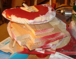
Since it had been several years since I’d made the Mini-H, I forgot all the particulars and had done three things wrong. First, I used liquid wax instead of paste wax. Secondly, the wax must be carnauba wax. And, lastly, the hair spray must be a “thick” hair spray. (With all the environmental concerns you can no longer find “thick” hairspray – the kind that makes hair really stiff.) You can see from the pictures that I had to completely destroy the pattern to remove it from the mold. And, most of the plaster was left attached to the mold. I soaked the mold in water and the plaster removed pretty easily.

Since most of the paint from the pattern also stuck to the mold, I had to scrape it off as well. It turned out that a table spoon had about the right curvature and worked well as a scraper. It removed the paint without damaging the fiberglass.
As is usual for me when I work with fiberglass there were several small air pockets in the mold. I use glazing to fill in these pockets and any other problems with the mold. Unfortunately, again, I’d forgotten how hard the glazing was to sand – especially on a concave surface. I applied glazing compound liberally to the surface of the mold. I ended up having to use a 3M sanding disc to remove the excess. It took quite a while, and I wasn’t real pleased with the final result.
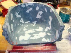
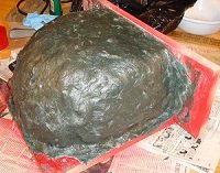
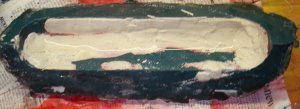
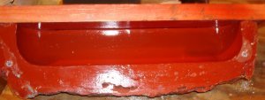
The left picture above shows the inside of the finished mold, and the right picture shows the outside of the mold while it was still on the pattern.
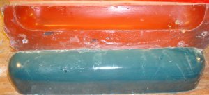
With the mold ready for use, I corrected some of the mistakes I had made. I found a carnauba paste wax and purchased a commercial mold release product from a local auto parts place. I painted the mold, waxed it 8 times, and applied the commercial mold release. The directions said it was best to spray on the mold release but it could be applied with a soft brush. I used a foam brush, and it worked well. I again used the short strand fiberglass next to the mold and backed it with a long strand fiberglass. After it cured I used a putty knife to break it loose around the edges. To my pleasant surprise, the part popped right out of the mold while I was working with the putty knife. From now on I’ll always use a commercial mold release product. No more hair spray for me!!!!
There is one other thing I need to mention here. I wanted the hood to be 10 inches wide. When I measured the finished fiberglass part, it was 10 inches wide across the inside of the top, but only 9 5/8 inches wide across the inside of the bottom due to shrinkage. Unfortunately again I didn’t take a picture of this, but I used two sections of 3/8” all thread, a coupler nut, and a couple small pieces of steel to spread the tank apart while it was still “green”.
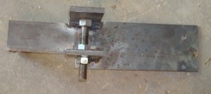
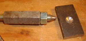
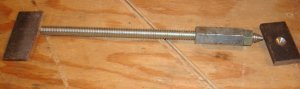 The two small pieces of steel were placed against the inside walls of the gas tank and the coupler nut was unscrewed forcing the walls outward until I got the 10 inch dimension I wanted. Notice the piece of steel on the right has a depression machined into it for the point of the all thread to set in and keep it from “walking” as it is unscrewed.
While the gas tank was now made, it required some finish work. I applied glazing compound (sparingly this time) to any air holes or depressions in the fiberglass tank. Since I was now dealing with convex surfaces, it was a lot easier to sand. It would have also been easier to use an electrical sander, but by applying the glazing compound in thin sections it wasn’t necessary.
Now that I’d completed the straight section of the hood and completed the gas tank, I could concentrate on a method of mounting them. I started by trimming the sides of the straight section of the hood. From the wood mock up I knew how high I wanted to mound the hood. I used two sections of ¼” by 2” flat to support the front section of the hood. In the picture below you can also see the location of the original gas tank.

I’ll discuss the horizontal section across the top later, but it adds strength and supports the front fiberglass section of the hood. The back section was a little more difficult to support. I didn’t want to just run two flats up like I did in the front. So, I bolted a section of ¼” by 2” flat to each side of the center section of the tractor frame and bent them outward and then upward to support the rear of the hood.
The horizontal section of ¼” by 6” flat adds to the rigidity of the vertical pieces and supports the fiberglass gas tank. It should be mentioned that the pictures above were taken after the ”real” gas tank was mounted. Since I knew where the “real” gas tank was going to be located I did not have it in position when I mounted the hood. The fiberglass “fake” gas tank mounts on the support shown above.
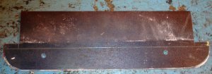
While I was shearing the sides of the hood to the correct height, I also made sections for the front lower portion of the hood.
You can see them in the picture above.
With the major portion of the hood completed, I turned my attention to the front section. I made a steel template of the section outline and c-clamped it in place.

I glued together several sections of wood and cut the rough shape on a bandsaw and sanded it into the general shape I wanted. I used plaster to obtain the final shape.
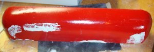
Notice in the picture there’s plaster on the painted part. I found that there’s a point where it helps to paint the part and then apply plaster. When you sand the plaster it’s much easier to tell when you’ve reached the original part. After the part had the shape and finish I wanted, I waxed it and applied mold release. With the experience I’d had with the gas tank, I spent a lot more time getting the front section smooth and rounded.
I fastened two boards to make sure the sides were flat and flush. The two boards had been painted, waxed and had mold release applied.

With the pattern made, it was time to add the short strand fiberglass.

I used long strand to backup and reinforce the short strand.
Notice the extra material at the top of the mold. That’s used to put screws through to hold a board in place to make a “back” for the mold. When I removed the pattern from the mold I was a little surprised that a lot of plaster came with it. My previous experience had indicated that the mold would release without bringing plaster with it.
You may notice some water in the mold in the picture above. I forgot to take the picture before I placed the mold in water to loosen all the plaster. I took it out of water for the picture. After the mold soaked overnight in the water, the plaster simply washed out. Any paint under the plaster easily flaked off because of the mold release. Again, I painted the mold, waxed it and applied mold release.

The board in the picture is used to make the back side of the mold. The fiberglass mold was screwed to the back board.
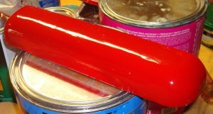
Now it was a matter of mixing hardener in short strand fiberglass and filling the mold.
After hardening, the casting was removed from the mold.
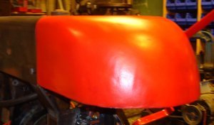
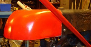
I set it in place on the front of the tractor to see what it would look like:
As usual, the casting had several small defects and small holes. The part was sanded lightly and glazing was used to patch all the defects. In the picture above, the steel mounting plate still extends out flush with the front of the casting. It eventually had to be moved back and made smaller so that the grill would fit without sticking out past the front of the casting.
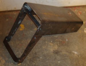
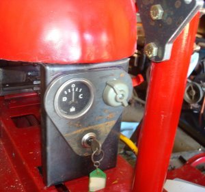
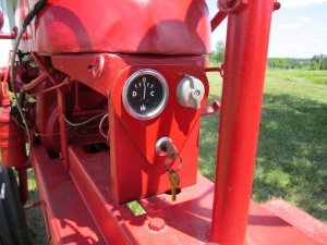
With the main sections of the hood completed, I turned my attention to other details. I needed an instrument panel at the rear of the gas tank to hold an amp gage, light switch and key switch. On the older model cubs there wasn’t a key switch, just a push pull switch for on and off. Since I’ll display the Mini-cub at shows, I wanted a little more security then provided by the simple off and on of a push-pull switch. To get the “standout” portion of the panel, I cut a section from ¼” steel.
I formed a rectangular box section from 16 gage steel, drilled clearance holes for the ammeter, light switch and key switch and mounted the section of ¼” steel to the front of it.
With the instrument panel constructed, I needed to mount the regulator and a starter switch before I could wire the tractor. I cut a 4” by 5” rectangular section from 16 gage steel, drilled holes and mounted the regulator using the two bolts that hold the starter in position.

The starter switch mounting was a little more complicated. The older model cubs had a push button switch mounted right on the starter, but my starter was not built for that. So I mounted the push button on the frame that held the hood and ran a wire to the starter. I used ¼” by 1” steel lever that would push the switch in when it was pulled to simulate the starting motion on the original cub.

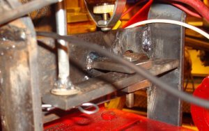
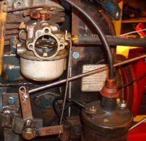
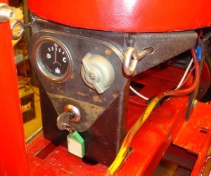
The choke was a little more complicated. I had originally intended to just use a choke cable like the one that was originally on the cub cadet. But since I’d made the pull starter to simulate the cub, I felt I should do the same thing for the choke. I mounted a bracket on the engine and connected a lever system to it. I ran a linkage from one of the levers to the choke and from the other lever to the instrument panel. In the picture below you can see the mount, the lever system and the two linkages.
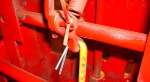
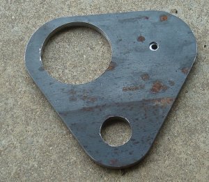
 Again came one of those sit, look and think sessions. (You’ll find you do a lot of those on a project like this.) There had to be a method and means of support for the starter control and choke control. At the end of the “think” session I decided to build a small triangular section to extend out each side of the instrument panel. I drilled a hole in each of the sections so that the controls could extend through. The sections were then welded to the instrument panel. Notice the holes in the triangular section for the choke and starter control to extend through.
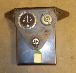
The looped section located on the left side of the instrument panel activates the choke, and the looped section on the right activates the starter.
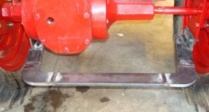
With the instrument panel completed, the tractor was ready to start and drive. But since it was still nasty weather outside the shop, I decided to work on the drawbar. The experience making the Mini-H drawbar helped with the construction of the drawbar for the Mini-Cub. I used the CNC mill to cut out the corner sections of the drawbar. I had measured and determined that the sides of the drawbar angled forward at an angle of 10 degrees.
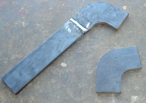
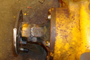
The picture above shows one corner section before it was welded and the other one with a section welded. The right axle support already extended down far enough to attach the drawbar. I used the CNC mill to make a bracket to connect to the right axle housing. The section was made from a piece of ¼” by 4” flat 5” long. This piece had a circular section cut out for clearance around the axle housing and two bolt holes. The bolt holes were used to mount the piece using the two bottom bolts that hold the axle housing in place.
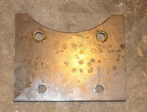
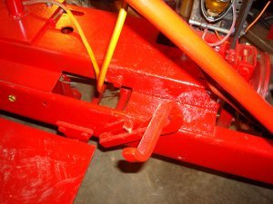
I had forgotten I had to drain the oil from the rear end until I removed one of the bolts and had oil running out. You can see the resulting oil spot in the picture below. I bolted a piece of 3/8” thick by 2” wide 4” long flat to each of the ¼” pieces. The drawbar pieces were welded to these two 3/8” pieces so that the drawbar could be easily removed. I remembered to take a picture of all that was necessary to hold the pieces in position. Notice in the picture there’s two c-clamps and a floor jack. The floor jack pushes up on a piece of flat that extends under both sides of the drawbar and pushes the sides up against the side supports.
With everything held in position I was able to mark the angle to cut the front sections as well as the rear center section. The final drawbar looked like this:

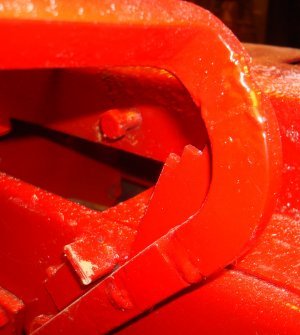
Notice the two vertical sections of 3/8” by 2” by 4” at the front of each side of the drawbar. To mount the drawbar to the tractor, those two sections are bolted to the ¼” by 4” sections that extend down on each side of the tractor. The finished drawbar sets a little lower then I wanted, but it had to be that low to extend out below the rear end of the tractor.
It’s easy to see the entire setup in the picture above. You can see the two corner sections, the rear center section and the two sections on each side that extend forward. It’s difficult to tell from the picture but each of the side sections extend forward at a 10 degree angle. Notice on the right side that the drawbar section that extends forward has been cut at an angle to mate with the 3/8” piece that’s bolted to the support. The same thing is on the left side but it’s not as easy to illustrate. After the drawbar has been painted the weld joint will be much harder to detect.
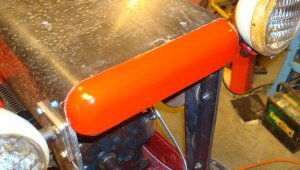
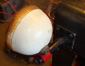
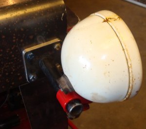
The next “finishing touch” was mounting the headlights. Again, a previous experience simplified this task. The lighting mount would be very similar to the Mini-560. I cut out two sections of ¼” by 2 ½” by 2 ½” on the CNC mill. I milled out a hole in the center of accept a ½” pipe as well as 4 mounting holes.
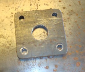

I pressed the ½” pipe in center hole and welded it on the back side. I drilled 4 corresponding holes in the front of the Mini-cub hood and mounted the lights.
Somehow, I forgot to mention the seat and the battery box. Both were built early on in the project so I could drive the tractor around. One of the first pictures in this article shows a temporary seat that I had installed. As soon as I got both rear axles in place, I installed a more permanent seat.


The seat is bolted to a flat that’s welded to a 1” diameter shaft that slides up and down in a 1” I.D. tube. A 3/8” bolt extends from the 1” diameter shaft through a slot to prevent the seat from rotating.
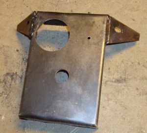
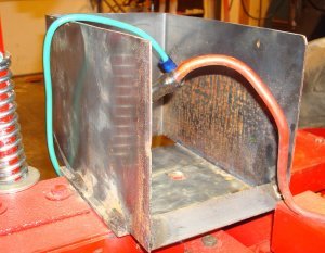
Once the seat was in place, I made a battery box and installed it under the seat. The battery box consisted of a piece of 16 gage sheet steel bent in a C shape and welded to a ¼” plate. The ¼” plate was bolted to the channel that supported the right axle. I placed a 1” by 1” channel across the front of the C shape to hold the battery in place.
Everything is now finished but the front grill and the painting. I need to find an appropriate material for the grill, and I need warmer, drier weather to do the painting.


Warmer weather arrived and I got the grill finished, painting done and decals added. The grill is a 1/8″ fine mesh screen wire that I purchased from McMaster Carr. It is held in position by a frame made up using 1/8″ by 3/4″ flat bent to the contour of the front grill.

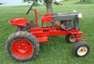
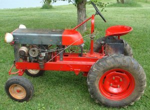
With the grill finished, I got the Mini Cub out for some pictures.

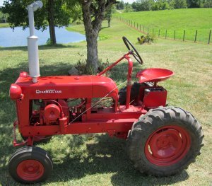

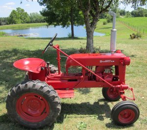
My plan is to make a belly mounted disk plow before I call the project finished. I want an implement for the tractor and a disk plow could stay mounted on the tractor for both storage and transport. When it’s finished, you’ll read about it here.
As always, I hope you enjoyed this article. And, if you have any questions or comments, feel free to contact me through this website.
