NOTE: This is an article that I’ve been working on quite some time. I have to go back and look up a lot of records to determine what I did and why so it’s going really slowly. I finally decided I’d go ahead and put what I have on the web and add/change it when I get time. So, if parts seem out of order or the end drops off rather quickly, that just means I haven’t had time to finish it. It will eventually be completed.
Note: I’ve completed the majority of the article. I hope to eventually add a small “G-code” program at the end. I hope you find the article useful and enjoyable.
I have found that a CNC (Computer Numerical Control) milling machine is a valuable piece of equipment for my hobby of making mini tractors (H, 560 and Cub) and implements to go with them. A CNC mill can be used to make necessary parts such as wheel spacers or add that special touch to an implement such as a mini-plow.
For a wheel spacer, a CNC mill will not only cut out the center hole for a piece of 2” diameter tubing, it will also accurately locate the holes for drilling and tapping for lug bolts. Likewise, a CNC mill will locate a hole pattern on a radius to allow for depth adjustment on a mini-plow – as well as cutting out a neat profile. Having a milling cutter controlled by a computer permits all kinds of interesting possibilities.

When I first got serious about my hobby, I had access to a CNC mill through my employer. I knew with retirement I would loose that benefit. So the year I retired, I decided to give myself a retirement gift of a CNC mill. While I have a basic knowledge of how “electrical things” work, I started this project knowing very little about what was required to build a CNC machine. My shop was too small to hold a full size milling machine (Don’t we always build them too small!!), and the small machines available on the market were not capable of milling steel parts the size I was interested. With a limited budget and a lot of unfounded confidence, I decided I would build my own machine. This article is the result of that process.
 The first step in the process was to find a mill that I could convert. After some research and reading several reviews, I settled on a Rong-Fu 31 mill/drill combination from ENCO. It has an 8¼ by 28 inch table with an 18 1/8” longitudinal travel (x-direction) and a 6¼ inch cross travel (y-direction). And, just when I had settled on the Rong-Fu it went on sale with free shipping. You can’t beat that for timing. I didn’t purchase the base as shown in the picture. I made my own.
The next step in the process required deciding on the type of motors that would be used for the conversion. With a little research, I discovered this decision involved deciding between stepper motors and servo motors. I don’t want to get too technical here, but while stepper motors are much easier to setup and install, servo motors permit a lot more control and accuracy. After some more research and because of my limited expertise in this area, I decided to go with the stepper motors. Basically, a stepper motor consists of a magnetic armature surrounded by field coils. By varying which coils current flows through and in which direction the current flows, the coils can produce a magnetic field which causes the armature to rotate (a north pole attracts a south pole type thing). The compete system works something like this: The computer sends the correct number of steps to a “controller” to move the mill table a specified distance. The controller “controls” a voltage source that produces the magnetic field in the stepper coils corresponding to each pulse to cause the stepper motor to rotate the correct amount for each step. The stepper motor rotation rotates the lead screw on the mill producing the desired movement.
While this is a simple procedure, there is one serious problem. Let’s say we want the milling table to move one inch in the longitudinal (x) direction. We program the computer to do that. It sends the appropriate pulses to the controller and the controller does its part. But, let’s assume the table hits a stop before it moves an inch. The computer and controller have no way of knowing that and are programmed to assume the correct distance has been achieved. If the table moves three quarters of an inch before hitting the stop, then all subsequent moves in the x-direction will be off by a quarter inch. The same thing can result with too high of a feed rate. If you program the computer to move the cutter at a feed rate faster then the stepper motors can power the table, there will be a discrepancy between the actual table movement and what the computer program thinks has occurred. (While a servo motor uses a feedback system to prevent this problem, the electronics are a lot more complicated and expensive.)
At the same time I was involved with ordering and installing stepper motors, I started looking at various software packages for the computer. I had previous experience using a couple different packages but they weren’t on a PC. I wanted one that was designed specifically for a PC and settled on a program called “Mach 3” published by Artsoft (http://www.machsupport.com/). Artsoft provides a trial download that can be used for programs less then 500 lines. It’s a reasonably priced program and there’s a forum to get any questions answered. It is a really great program. I’ll include a sample program later in this article if you’ve never worked with CNC code (called G-code) before.
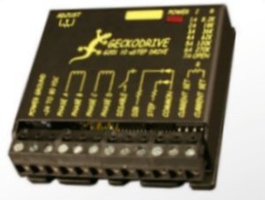
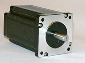 With the software selected (and actually while I was looking at different software packages), I was looking at stepper motors and controllers. With no real expertise in this area, I wanted to go with “plenty big” to make sure the motors were powerful enough to move the mill table without missing any steps. I selected a 500 oz-in Model No. RS23-500 stepper motor sold through http://www.homeshopcnc.com/ . The RS23-500 has a rated voltage of 3 volts and a rated current of 3 amps (That’s important information as you’ll see later). These motors are bipolar 4-wire, 2 phase and have a 1.8 degree step angle. When I did all the research I could explain what all that meant. For now, the important stuff is that it has 4 wires (two circuits) and a 1.8 degree step angle. Homeshopcnc has a promotion that allows the purchase of a Geckodrive G201 controller at a reduced price with the purchase of each stepper motor. The G201 is manufactured by Geckodrive Motor Controls (http://www.geckodrive.com/). Originally I only purchased one stepper motor and controller to make sure I could get everything to work. Eventually I purchased a total of 3 stepper motors and 3 controllers – one for each axis of the mill. I should also mention here that the 500 oz-in was just a really wild guess. I used a spring scale to measure the force I had to apply to the horizontal feed on the Rung-Fu to get an approximation of the torqure required. I went “plenty big” from the value I obtained.
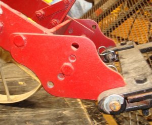
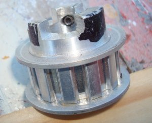
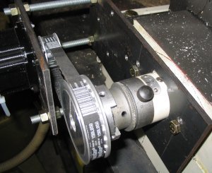
Mounting the stepper motors was one of the easiest parts of the process. I made plates to hold the stepper motors and mounted them by using longer bolts in the end supports for the x and y lead screws. The plates had slots machined to allow for final belt adjustment. I purchased timing belt pulleys from D J Manufacturing (http://www.janick.com/dj/). I found D J Manufacturing to be a very good company to deal with. I used a 2 to 1 reduction from the stepper motor to the lead screw in order to double the torque from the motor to the lead screw. All the timing pulleys were double flanged with a 3/8” pitch and a ½” belt width. The pulley on the stepper motor had 12 grooves and the one on the lead screw had 24 grooves. For the pulley that went on the end of the lead screw, I cut out material to match the hand pulley mounts. The pulley shown is one purchased when I’d planned to have a 1 to 1 ratio on the pulleys. The 2 to 1 reduction gave me more torque, and the Mach3 software has an easy way to handle the speed reduction between the stepper motor and lead screw. The timing belts were purchased from McMaster Carr (http://www.mcmaster.com/). There’s an exact formula that can be used when you pick a center distance between your pulleys, but you can get a close approximate by adding half the circumference of each pulley to twice the center distance. I actually calculated the center distance, but if you make provision for some adjustment the method I mentioned above should be close enough. The formula is pretty complicated.
The x-axis mount looks like:
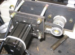
It’s not easy to see in the pictures, but the plate that holds the stepper motor is connected to the plate connected to the mill with three pieces of all thread. That allowed for adjustment in and out to align the two pulleys. You can see the two bolts that holds the plate to the mill table.
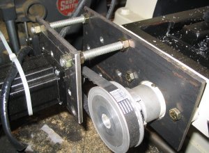
The y-axis mount looks like:
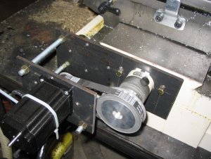
Since the y-axis drive is mounted to the milling machine base rather then the table, it had to be mounted lower to allow the table to move over the top of it.
The z-axis presented a greater challenge. There was no easy method of connecting a supporting plate to the spindle depth control. There were some mounting holes that would’ve been used if I’d purchased the power feed option. So, I made a bracket that ran from that location at the back of the machine to the front that could be used to mount the stepper motor.
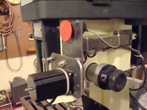
Because of the limited space available the z-axis used a 1 to 1 reduction drive. Again, the Mach3 software easily accommodated the different speed reduction. As can be seen in the photo above, the z-axis support also was the location of the E-stop (emergency stop).
 With the hardware all mounted, it was time to return to wiring in the controls. The G201 connects to the computer through the computer’s parallel port. I purchased an interface board to simplify the wiring between the computer and controller. The interface board is a C1G – Parallel Port Interface Card manufactured by CNC4PC (http://www.cnc4pc.com/). The C1G card allowed me to run a standard parallel cable from the computer to the card without messing with a lot of small wires. The C1G has a screw terminal for each pin on the parallel port connector. For someone that didn’t want the hassle of trying to identify which pin was connected to which small wire, that made the connections a lot simpler and bullet proof. Individual wires are run from each screw terminal on the C1G card to each controller (3 wires to each controller). The C1G interface card also allows for the simple installation of an emergency stop and “home” limit switches. I used the emergency stop function but not the home limit switches.
Fortunately for the “electronically challenged” the Gecko website has a lot of useful information and simple schematics. I found their basic tutorial to be very useful. (http://www.geckodrive.com/upload/Step_motor_basics.pdf) If you just scan through the beginning of the article, the middle of the article contains the good stuff – how to power your stepper motors. As mentioned earlier, the controller (powered by a 5 volt d.c. source) controls a power source to the stepper motor field windings to energize them and cause a step. Gecko recommends an unregulated power source capable of supplying from 3 to 25 times the motor’s rated voltage. (The higher voltage can be used because of the manner in which the G201 pulses each step. A continuous voltage of that magnitude would cause the motor to overheat.) Since the motor I chose is rated at 3 volts, I needed a power source that supplied between 15 and 75 volts. Below is a schematic for an unregulated power supply.
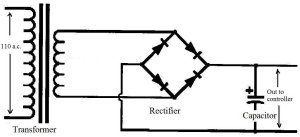
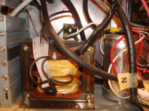
I located a 24 volt (12 amp) transformer which will produce around 34 volts output to the controller – (1.414 * 24 = 33.94) — it’s an electrical thing!!! The rectifier had to be capable of handling 9 amps. (Worst case, the motors each draw 3 amps. 3 motors X 3 amps/motor = 9 amps.) A friend supplied me with a rectifier capable of handling 10 amps. The Gecko website gives an equation to calculate the minimum required capacitance based on the motor’s rated voltage and current. (C = 80,000 * I/V) Since the motor I chose has a rated current of 3 amps and the supply voltage is 33.94, C = 80,000 * 3/33.94 = 7,071 microfarad. I located a 13,000 microfarad, 24 volt capacitor, and I was ready to start wiring.
I located an old computer and removed all the “internals” except the on/off switch and the power supply. I originally used the computer power supply to supply 5 volts d.c. for the C1G and the G201. But, when I first tried the system, the computer power supply did not supply enough current. So, a good friend supplied me with a 5 volt d.c. power supply capable of doing the job. Sorry that I can’t tell you much more then that about it, but he just said it was “plenty big enough.”

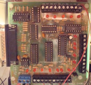 On the left is the C1G schematic supplied by the manufacturer. On the right is a picture of the actual board. The wiring is pretty simple. (Selecting all the components is the hard part.) A parallel interface cable is run from the computer to the C1G. (The connector is on the middle of the left side of the board in the picture.) The Mach 3 software lets you specify the output for each pin of the parallel connector. You can also specify a pin to use as an emergency stop (Estop).
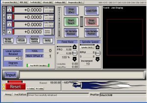
I downloaded the Mach 3 software and installed it according to the manufacture’s instructions. The opening menu for the Mach 3 software looks like:

Each of the stepper motor controllers (G201 controller) must receive two signals (a signal to step and a signal to indicate the direction) as well as a common (ground) from the C1G board (which receives it’s signal from the computer). The Mach3 software allows you to specify what signal is sent on each pin number. Notice the top menu of the Mach3 software contains a “Config” tab that can be used for this purpose.
![]()
The drop down menu for the Config tab is:

I’ll talk about some of the others later, but for right now we’re just interested in the Ports and Pins selection. The Ports and Pins menu is used to assign outputs to the parallel port pins. Selecting Ports and Pins:

Notice from the figure above that for the way I have it set up for the x-axis, Pin 2 is used for the direction and Pin 3 is used to indicate a step. Likewise Pins 4 and 5 are used for the y-axis and Pins 6 and 7 are used for the z-axis. That means that screw terminals 2 and 3 on the C1G board will have the outputs for the x-axis, screw terminals 4 and 5 will have the outputs for the y-axis and terminals 6 and 7 will have the outputs for the z-axis.
The 5 volt supply (and ground) is also connected to the C1G (lower left corner in the picture). +5 volts must also be supplied to the EN position shown in the lower left corner. This connection can be used in conjunction with the G201 for an emergency stop. Three wires must be run from the C1G to each of the G201 controllers corresponding to a step command, a direction command and common (ground).
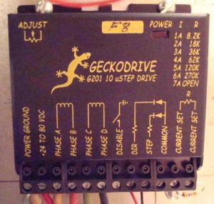 Since the wiring for each axis is basically the same, I’ll just explain the wiring for the x-axis. The cable that runs from the computer to the C1G is a standard parallel cable. Additionally, as explained above, the 5 volt supply has to be connected to the C1G. Next is the wiring for the G201 shown at the left. The common and voltage from the unregulated power supply connects to the first two terminals (bottom left in the picture). The G201 instructions recommends a fuse be placed in the voltage line between the unregulated power supply and the G201 connection. I used a 5 amp fuse. The next 4 connections are for the 4 wires from the stepper motor. The important thing here is to make sure the connections to Phase A and Phase B make a complete circuit and the connections to Phase C and Phase D make a complete circuit. I used an ohm meter to check for continuity to determine which pair of wires on the motor formed a completed circuit. Either pair can be connected first. If after everything is connected and running the stepper motor rotates in the wrong direction, just switch the connection from Phase A to Phase B and from Phase B to Phase A. That will reverse the direction of rotation. I didn’t use the next connection — Disable. For the x-axis, I ran a wire from Screw Terminal 2 on the C1G board to the Dir connection on the G201 (Remember this was specified in the Mach3 software). Likewise, the Step connection required a wire from Screw Terminal 3 to the Step connection on the G201. Additionally, a wire was run from a Common Screw Terminal on the C1G (there’s lots of common terminals available) to the Common Terminal on the G201. The value of the resistor that goes between the last two terminals can be determined from the table on the G201 module. Since the stepper motor I used was rated at 3 amps, I located a 36K ohm resistance and connected it between the two terminals. And, that’s the wiring for the x-axis.
The wiring for the other two axes is basically the same. Obviously the Direction and Step connection would have to be with the correct connection on the C1G. Also, the G201 instructions specify that independent connections must be run from the unregulated power supply to each G201 contoller and each connection should contain it’s own fuse.
And that’s all the wiring. There’s still some “software stuff” that has to be done before the system is ready to go, but we’re getting close!!!
For the system to work properly, the Mach3 software must send the correct number of pulses to the stepper motor to get the exact movement required. Remember the Config menu:

Selecting “Select Native Units”

I set my system for Inches since my lead screw used inches. The Mach3 manual has a good discussion on using mixed units if one so desired. With the units set, I could configure the software to match the motors. The lead screws on the mill had 10 threads per inch or a pitch of .1 inches/thread. That means the lead screw has to turn 10 revolutions/inch. Since I used a 2:1 reduction from the motor to the lead screw, the stepper motor must turn 20 revolutions/inch of table movement in the x and y directions. (Remember the z-axis was 1:1 so that stepper motor would turn 10 revolutions/inch.) The stepper motor moves 1.8 degrees per step. So, it would require 200 steps/revolution. (360 degrees/revolution / 1.8 degrees/step = 200 steps/revolution) The G201 sends out 10 pulses/step. (That was in the literature – it’s nothing to be calculated.) Since it takes 200 steps/revolution and the G201 sends out 10 pulses/step, it will require 2000 pulses/revolution. (200 steps/revolution X 10 pulses/step = 2000 pulses/revolution.) Therefore, the Mach3 must send out 40,000 pulses/inch (2000 pulses/revolution X 20 revolutions/inch = 40,000 pulses/inch). While this may seem a little complicated if you’ve never dealt with it before, the Mach3 manual does a good job of stepping you through the process. What we need to know is that it requires 40,000 pulses/inch for the x and y-axis and half that, 20,000 pulses/inch, for the z-axis.
Now, again under the Config menu, there’s a Motor Tuning option:
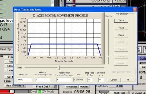
Enter 40000 in the Steps per box. The Mach3 manual has a good discussion on setting the velocity and acceleration, but I just tried it and found what would work. Be sure to save your settings and repeat the procedure for each axis.

The system is now ready to try out!!! I did all my trials before actually installing the timing belts to make sure everything was working properly. The easiest way to make a quick check is to hit the “Tab” key and the Mach3 software displays:
And you can mouse click on the appropriate axis to “Jog” it to a new location. Holding down the “shift” key while you click on the appropriate tab will result in rapid traverse. If everything is installed correctly, the axis you’ve chosen should move. Note: You’ll have to hit the Reset button on the opening menu before you can jog any axis. The red button above the Reset button should turn green if everything is ready to go.
The other method of checking your work is to use the “Immediate Mode”. Notice on the opening menu, there’s several menu selections:
![]()
Selecting the second menu item (MDI Alt2) puts you in the immediate mode:
Entering a command in the Input line and hitting the return key will execute that command. Again, I should point out the button above the reset button must be green; not red as shown in the above picture.
And, that’s it. The Mach3 has a world of capability not discussed here. There’s a lot more that you can do with it, but I’ve just covered the basics here. There is one more thing you must do before doing any actual machining. Under the Config menu you may have noticed a “Backlash” item. Before doing any milling you must determine the amount of backlash for each axis and enter it here:

Be sure you check the “Backlash Enabled” box.
And, that’s it. As I said at the beginning, this was completely out of my area of expertise. For that reason it was one of the most satisfying projects I’ve completed and, to be honest, I was rather proud of myself when it all worked. I learned a lot and I’m sure I’ve forgotten over half of what I learned. One of the main reasons for writing this article was so I’d have a record if I ever need to change or redo something. I’m not a machinist by trade or training so I just use the basic stuff from the Mach3. But, if you are a machinist or plan to do some serious machining the Mach3 has a whole lot more capability then what I’ve discussed here. I barely touched on it’s capabilities above.
Here’s a picture of the finished project. It’s hard to get a good picture where it’s located in my shop, but this should give an idea of what it looks like:

I hope you find the article useful. If you plan to convert a mill, I hope you get as much enjoyment out of the project as I did. I didn’t keep a real accurate record, but I think the entire conversion cost me around $600 not including the cost of the mill. Of course, I had the electronics for both the 5 volt and unregulated power supplies given to me by friends.
When I get a chance I’ll add a simple G-code program to this article. I’m planning on illustrating how to cut a 1” long, ¼” slot in a 2” by 2” piece of ¼” steel. That’s pretty simple but it will illustrate how simple G-code programming can be.
As always, if you have any questions or comments, you can contact me through this website.
