I’ve owned Cub Cadets since 1978. We first purchased a 122 and a short time later purchased a 102 to mow our lawn. (It’s a large lawn.) My wife wanted to use one of the Cub Cadets to do garden work so I built her a small trailer to haul flowers, plants, fertilizer, weeds, etc. Since we have a lot of fenced in pasture, the trailer also turned out to be handy for hauling fencing supplies. At first, I would load and unload fence supplies every time I needed to repair or replace fencing. As our fence got older more and more supplies were left on the trailer. It eventually became a dedicated trailer for fixing fence and my wife no longer had use of it for gardening.
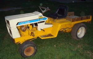
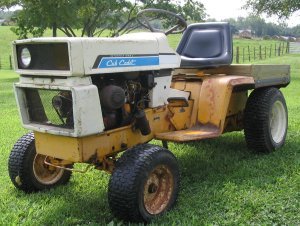
My wife made it clear that she was in need of some kind of vehicle to use for gardening. So, I purchased a 1650 roller and a 129 roller to make a utility cart. The 1650 originally only had one headlight, so the utility cart was named “Wink” and it stuck. Although there are a few times when my wife could use a utility vehicle with a larger carrying capacity, the majority of time she only needs something that’s capable of carrying small, heavy items. For that reason, and for appearance, I made Wink with a bed that is 30 inches by 30 inches.
I began by removing the rear ends from both rollers. For the 1650, that meant disconnecting the hydraulic lines that run the hydrostatic drive. On the 129 frame, I measured 30 inches from the rear of the frame on both sides and drew a vertical line and used a Sawzall to cut off both rear sections. On both sides of the rear of the 1650 frame, I c-clamped a 3 foot section of angle so that a foot and a half of the angle extended past the rear of the frame. I c-clamped the two pieces of the 129 frame to the extended section of angle iron. The angle iron kept the 129 frame sections lined up with the 1650 frame. I welded the 129 sections to the rear of the 1650 sections on the outside of the frame. I cut two additional 2” wide sections of the 129 frame and placed them on the inside of the 1650 frame where it joined the 129 frame pieces. These sections overlapped the splice and were welded in place to add additional strength to the weld joint.
With the length of Wink extended, the next problem was to get the drive shaft and hydraulic lines extended. I didn’t want to mess with the iso-mounts so I made some solid mounts on a lathe to replace them. I took a ¾” shaft and turned it down to 5/8” on both ends to fit the 1650 connectors that were already in place on the engine and transmission. After I got the hydraulic lines connected and tried the drive shaft, I discovered I had a problem – the center of the shaft moved in a circular orbit. As the engine speed increased this orbit became a 2 inch diameter circle. To stop this shaft movement, I mounted a ¾” bore pillow block near the center of the shaft.

You can also notice that the drive shaft is spliced in the above, left picture. A splice at this point made the shaft easier to remove and replace.
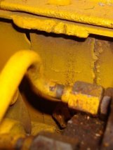
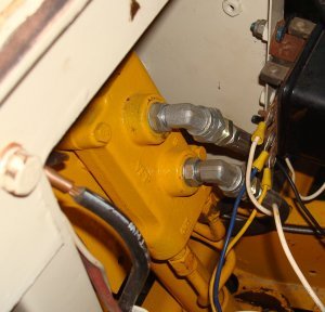
After the original version of the drive shaft was in place, the hydraulic lines had to be connected before I could make a test run. I contacted a hydraulic shop about making new hydraulic lines. Instead of new lines they suggested an alternative. I knew approximately the length I needed for the new lines. They made a splice section a little longer then I needed and enlarged both ends of both sections. The long flared sections allowed me to adjust the final length after the lines were placed in the tractor. I installed both ends of each line with the sections that the hydraulic shop had made installed in the center. All that was required was to silver solder them in place.
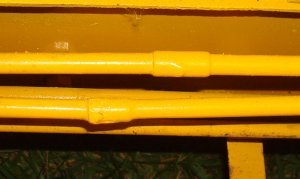
The top picture is the rear connections, and the bottom picture is the front connections.
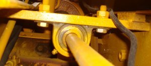
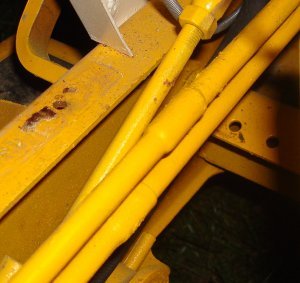
It was fairly easy to make extensions for the controls. The one change that was made was an increased diameter for the rod that controlled the hydrostat. Since the rod would now be significantly longer and in compression, buckling would be a problem. On the ends I used sections of the original control linkage and added a ½” diameter rod to connect the two sections.

A 3/8” rod was used to extend the rod used to return the hydrostatic control to neutral since that rod would always be in tension. That rod can be seen below the ½” diameter rod in the right hand picture above. (The two hydraulic lines are seen on the top of the picture and the 3/4″ drive shaft is on the very bottom.)
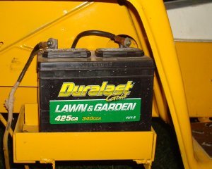
The rest of the process was pretty routine. I mounted the seat and original fenders and cut them off right behind the seat. Finding a place to mount the battery turned out to be a little bit of a challenge. The original location under the seat couldn’t be used since the drive shaft and hydraulic lines now ran through that section. I finally found room under the right fender in front of the rear wheel. I made a box to mount the battery in and attached it to the frame of the tractor.
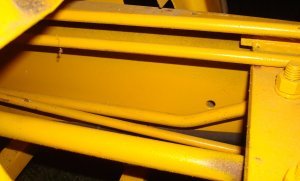
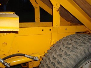
I used two 2” by 3/16” angle irons to extend the bed over the rear so it could later be made to pivot. (They’re the rusty sections in the picture below.) The bed itself was made of 2” by 2” by 1/8” angle and is the grey steel in the picture below.

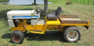
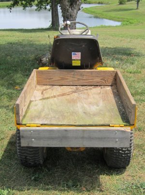
Later I added additional angles the length of the bed and more towards the center to add support and provide a place for the pivot arms for the dump mechanism to be connected. After placing a ½” thick piece of plywood in the bed and adding sideboards, Wink was ready for temporary use.
We used Wink the way it appears in the above photo for a couple of years. Eventually I decided to paint it and add a hydraulic lift to the bed so it could dump. The original cylinder and auxiliary hydraulics had been left in there original location on the 1650. Previously I had removed the lift mechanism from the frame of another 1650 that had been used for another project. I had also cut out the bushings from the frame so there would be additional support when I remounted the lift mechanism in the rear of Wink. Since the cylinder did not have enough stroke to give the necessary lift height, the pivot arms had to be extended.
I purchased new connections to use at the hydraulic control valve and ran ¼” hydraulic hoses to the rear cylinder.
Wink was ready to use. It has proved to be one of the most useful Cub Cadets that we own. I’ve used it a couple of times for fencing, but I’m not going to make a habit of that!!!!
Here’s some pictures of the finished project:


As always, I hope you find this article useful. And, if you have any questions or comments feel free to contact me through this website.
