
Voltage Regulator Wiring
Bat — connects to the battery (Gray wire if original wiring); may connect to the battery through an ammeter and key switch
Gen — connects to the armature terminal on the starter/generator (light blue wire if original wiring); armature terminal will also have wire from solenoid
F — connects to the field terminal on the starter/generator (yellow wire if original wiring); only wire on the starter/generator field terminal
Gnd — connects to ground on tractor frame (white/blace wire if original wiring)
How a voltage regulator works
In all the discussion that follows, when I refer to the generator, it’s actually the starter/generator used on older model Cub Cadets. The discussion also refers specifically to the type of regulator shown above. CAUTION: A battery can explode as a result of a spark or overcharging. Wear appropriate safety gear when working on the charging system, especially safety glasses.
At the left is a “pictorial schematic” of what I think the wiring is on the voltage regulator. Again, I take no responsibility for the accuracy of this schematic. Without destroying the regulator, I couldn’t check all the connections I’ve shown. Notice the points on the left are normally closed and those on the right are normally open.
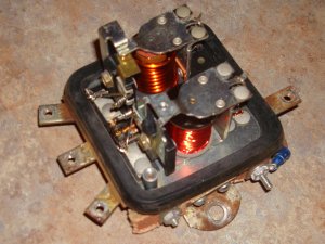
The voltage regulator has two functions. 1) Regulate the voltage to the battery so it doesn’t exceed 14 volts (actually 14.2 volts). 2) Disconnect the battery from the generator when the voltage from the generator gets too low as when the generator is turning slowly or stopped. In the picture of the regulator above, the coil on the bottom regulates the voltage (regulator coil) and the top coil (cutout coil) disconnects the battery from the generator. I had to troubleshoot the bottom section of the regulator and this discussion centers mainly on that portion. In the schematic, the regulator section is on the left and the cutout is on the right.
If the field terminal on the generator is connected directly to ground, it will produce a voltage at the armature terminal of the generator. This voltage will exceed 16 volts and will overcharge the battery if not regulated. For the voltage regulator pictured above, a wire from the field terminal of the generator would be connected to the field terminal of the regulator (bottom left side of picture). The field terminal of the regulator is connected to ground (bottom right terminal in the picture) through the lower set of points shown in the picture. (The frame of the points is insulated from the base of the regulator.) This connection is shown in the schematic by a green line. If the points remained closed, the generator would produce over 16 volts and overcharge the battery. The points must open to “unground” the field terminal of the generator and prevent overcharging. On an actual voltage regulator, one end of the regulator coil wire is connected to the generator terminal of the regulator (center left terminal) and the other end is connected to ground. As the generator voltage increases, the magnetic pull of coil on the points increases. When the voltage at the generator terminal reaches around 14 volts, the magnetic filed generated by the coil pulls the bottom section of the points downward, breaking the field connection to ground. With the field connection disrupted, the generator output voltage drops, the voltage to the generator terminal of the regulator is reduced, the magnetic force of the coil is decreased and the spring pulls the points closed again. The points alternately open and close to regulate the voltage output. This whole process occurs so rapidly that the output voltage remains around a constant 14 volts for all practical purposes.
The procedure I used to check the regulator section of the voltage regulator
The system I checked was only outputting 4 volts at the generator armature. I used the following procedure to diagnose the problem. This procedure assumes that you’ve checked all connections and grounds to make sure they’re good. With a properly working voltage regulator, you should read around 14 volts between the armature connection of the generator to ground. If the system is not outputting 14 volts to charge the battery, follow this procedure. Leave a voltmeter connected from the armature connection of the generator to ground for these tests. You’ll need a couple jumper wires (two wires with alligator clips on each end works well), an ohmmeter, and a voltmeter with a range of 0 to 16 volts. I prefer an analog meter for these checks but a digital voltmeter can be used. You can jump ahead on these checks and work backward through the procedure if you suspect a particular problem. The procedure also assumes the generator is outputting less then the required 14 volts before each test is performed. Once you get 14 volts, further testing will do you no good.
First, check that the generator is capable of outputting the required voltage. Connect a jumper wire to a good ground. With the engine running at a fast idle, temporarily touch the other end of the jumper wire to the field terminal on the generator. (Don’t race the engine for this test or you can overheat and burn something up.) The voltmeter should rapidly read above 16 volts. (Don’t operate the regulator over 14 volts for an extended period of time.) If voltmeter reading doesn’t exceed 16 voltss, recheck your ground and try running the engine a little faster. If the generator still fails to reach 16 volts with this test, it needs to be repaired and/or replaced.
Assuming the generator passes this test and with one end of the jumper still connected to a good ground (and the engine at a fast idle) touch the other end of the jumper to the field terminal (marked F) on the voltage regulator (bottom left hand connection in the above picture). Again the voltmeter should read above 16 volts. If it doesn’t, you have a bad connection or wire between the generator and the voltage regulator.
With the cover of the voltage regulator removed, touch the jumper wire to the left side (fixed side) of the point bracket. Again the voltmeter should read above 16 volts. If it doesn’t you have a bad connection between the regulator terminal and the left side of the points. In the regulator picture above, there’s a silver wire that makes this connection.
Next, touch the jumper to the right hand side of the points (somewhere around where the spring is connected on the right hand side in the above picture). If the voltmeter fails to register above 16 volts, there’s poor contact across the points. Shut off the engine and drag a sheet of paper back and forth through the points. Use your ohmmeter to check the resistance. It should read something less then one ohm. Continue to clean the points until you get this reading. If your system is still not charging when you restart the engine, again make the above ground check to make sure you’re getting a connection through the points. When the system is working properly these points will rapidly open and close to produce a 14 volt charge to the battery. IF THE POINTS STAY CLOSED YOUR POINTS ARE STICKING OR YOU HAVE A BAD COIL. There is a possibility that the spring tension is too high but I’ve never messed with the spring tension.
Assuming the system passes all the tests above, touch the jumper to the ground terminal (marked GND) of the voltage regulator (bottom right terminal in the above picture). If the voltmeter reads above 16 volts during this test, then the regulator is not properly grounded. You now have checked the complete field circuit and the voltage regulator has the same effect as shorting the field at the generator directly to ground.
Again, the voltage regulator shown consists of two coils. The lower coil (in the pictue) with the smaller windings “regulates” the voltage; i. e.; it causes the generator to charge at around 14 volts. The top coil (with the heavier windings) is used to disconnect the voltage regulator from the battery when the engine is not running or running too slowly to charge the battery. Otherwise, the battery would discharge through the voltage regulator and generator windings when the engine isn’t running.
Unfortunately, I couldn’t figure out a way to check the individual coil resistances to make sure the coils were good. Notice in the schematic there is a connection between the GEN terminal and GND for both coils. So you cannot check the resistance of either coil individually without cutting a wire and I didn’t want to do that.
As I explained earlier, I know the function of the top coil and points in the picture. But I can only speculate how they work. This portion of regulator I was working on worked properly so I had no reason to investigate further. I do know that with the generator producing the correct output voltage (14 volts), the magnetic pull of the top coil pulls the top points closed connecting the generator to the battery. That will allow the 14 volts being produced by the generator to charge the battery. Notice there are two sets of windings on the coil. When the generator output reaches somewhere around 14 volts, the magnetic force produced by the coil that connects the generator terminal to ground will pull the points closed connecting the armature to the battery. (The red line in the schematic) The coil windings in the “red line circuit” add additional magnetic pull on the points to help hold them closed. When the voltage output from the generator drops below battery voltage, current from the battery will flow from the battery to the generator (reversed from the direction when charging). This creates a magnetic force that opposes the magnetic force produced by the other winding on the cutout coil allowing the spring force to open the points and break the connection between the generator and battery. The open points prevent the battery from discharging through the generator.
I can tell you how to check the point connection for this section (the cutout section), but it’s a bad way to test!! With everything connected and the engine shut off, if you manually close these points, it will cause the starter/generator to turn. If you look at the schematic you can see this would connect the battery to the armature causing rotation. But, this is a really bad idea for a couple of reasons. First, you’re running starter current through a wire that’s not large enough to carry it. The wire that runs from the solenoid to the armature that’s used to start the engine is 10 gage. The wire in the charging circuit is probably only 14 gage. The second reason not to do this is that there’s a good chance the points will stick closed. So, in summary, it’s NOT A GOOD IDEA.
If anyone has additional insight into how the regulator works or has a correction to any of my above discussion, I’d be glad to hear from you. In any correspondence, please indicate if you wish for me to acknowledge your help. Be aware, however, if I receive the same information from two individuals and one doesn’t want acknowledgment, I’ll obviously use the information from that source. I’ll be glad to furnish anyone with documentation to that effect. Thanks in advance for any help.
Addendum: I decided since I was at it, I’d include a short discussion of a later model regulator as well.
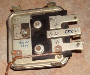

Notice that this regulator has the “GEN” terminal located on the back side. The regulator coil is the bottom coil in the left hand picture and the cutout coil is on top. From the bottom of the left hand side to the top, the terminals are: “F”, “BAT” and “L”. You can see the “GEN” terminal in the picture on the right. It’s centrally located on the left side of the back in the picture. The regulator base acts as the ground.
How it works
I think the “pictorial schematic” should look something like this:
 Although the regulator wiring looks a little more complicated, it seems it should work and be debugged in the same way. Notice that the field terminal is initially connected to ground (green circuit in the schematic) and opens as a magnetic field is built up by the voltage from the generator. Again, as the generator voltage increases, the points would open breaking the connection to ground and regulating the voltage. If you notice on the picture of the back side of the voltage regulator, there’s something that runs from the field terminal, across the back of the regulator and grounded to the case. I think this is just a resistor. This would mean that under operation, the field connection would never be completely broken from ground. (See the pictorial schematic) There would always be a connection to ground through this resistance. The first regulator I discussed also had this resistance, but I left it out of the schematic to simplify the discussion. I don’t know for sure, but have a feeling it’s used to smooth out the voltage and maybe save some wear and tear on the points by reducing the magnitude of the current flowing through the points. With the resistance in the circuit, the field winding connection to ground will never be completely broken so that the voltage would never tend to drop to completely zero if everything is working properly.
This time there’s two windings on both coils. The two windings on the cutout coil would behave just like the two windings on the cutout coil discussed earlier. It seems that the second winding on the regulator coil would help open the points and produce additional voltage regulation. Also, notice that the “L” terminal will always be at the same voltage as the “BAT” terminal. There is a direct connection from the “BAT” terminal to the “L” terminal within the voltage regulator. I think the “L” terminal is generally used to supply voltage for the auxiliary circuit on a Cub Cadet.
As mentioned previously, if you can add additional information on how this regulator works or a good trouble shooting procedure, please let me know. Any place in the discussion that I use the expression “I think”, I could use some verification that my thinking is correct. As before, let me know if you want acknowledgement for this help placed in the discussion.
Voltage Regulator Wiring
L — assesory wiring (may have no wire connected if no lights)
Bat — connects to the battery (Gray wire if original wiring); may connect to the battery through an ammeter and key switch
F — connects to the field terminal on the starter/generator (yellow wire if original wiring); only wire on the starter/generator field terminal
Gen — connects to the armature terminal on the starter/generator (light blue wire if original wiring); armature terminal will also have wire from solenoid
As stated above, the ground is the regulator case and mounting
