Clutch Removal and Disassembly
I’ve seen (and used) methods of removing the clutch without completely removing the engine. But, with experience, I’ve learned that just the little amount of time it requires to remove the engine makes the whole procedure go easier and, in the long run, quicker. The first thing to do is to discount the ground wire on the battery. There’s no need to disconnect the positive wire as well.
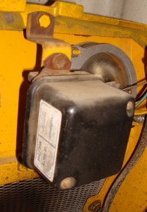
After removing the ground, remove the hood. Remove the two bolts that hold the voltage regulator in place and place it aside. If you use a little caution in how you handle it, there’s no need to remove any wires. (There’ll probably be a ground wire connected to one of the bolts that holds the regulator in place. Don’t forget to replace it when reassembling.) Loosen the lock nut on the PTO engagement rod and unscrew the coupler nut on the rod.

Next, remove the grill and grill housing. If the tractor was manufactured before 1966 and has a mule drive attached, you’ll have to remove that first. For tractors manufactured after 1966 just release the lever that holds the mule drive in place and pull it off.
The two rear bolts in the mule drive are just studs and easily removed. For the front two bolts I use a 3/8” socket and ratchet to hold the nut on the inside and a ¾” in ratchet wrench to turn the bolt.
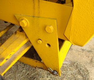 For the four bolts that hold the grill housing in place, use a 9/16” open end wrench to hold the bolt on the inside of the frame and a 9/16” deep well socket to loosen the nut under the frame. Remove the grill frame and set it aside. If this is the first time you’ve gone through this procedure, it will probably take you 30 minutes or better. If you’ve done it before, it should take no more then 10 to 15 minutes. Either way, you’ll make the rest of the job a lot easier and, in my opinion, save time and smashed fingers.
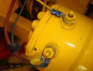
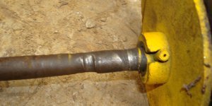
Before removing the engine, remove the rear spiral pin in the drive shaft. (Read the section on Coil Pin Removal in the Tips and Tools section of this website if you have a problem with this.) After the rear spiral pin has been removed, disconnect the wires from the starter generator. There should be two wires connected to the armature terminal and one to the field terminal. I always tape the two wires together so I know which wires are to be reconnected to the armature terminal.
Remove the wire from the plus terminal of the coil. Disconnect the throttle and clutch cables from the engine.
Before removing the clutch, the connection to the clutch pedal must be disconnected. I’m generally able to do all the rest of this process without getting under the tractor. But I’ve found no way to make this disconnect without getting under the tractor.

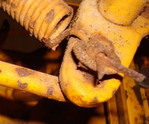
Removing the clutch pedal return spring is generally a lot easier then replacing it. Unless it’s been removed recently, the connection probably looks like above. After removing the cotter key I just slide the spring off the end. As you can see in the picture on the left above, the opposite end of the spring connects to the tractor frame. Getting the clutch pedal return spring stretched and reinstalled can be a real pain. And, again, I’ve always had to do that laying on my back under the tractor.
Now remove the four bolts that connect the engine to the frame and the engine can be removed. I’ve always been able to remove these bolts sitting on a stool and reaching under the frame. I don’t like to work under the tractor unless I have to. After removing the bolts, I generally lift the engine out of the frame and set it aside rather then just moving it forward in the frame.
After you remove the pin that the clutch release lever pivots on, you can slide the clutch forward and remove it from the tractor.
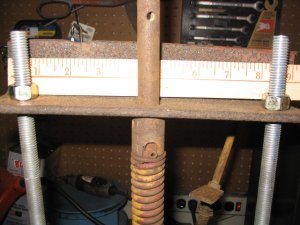
I made my own compression tool to disassemble the clutch assembly. It consists of two pieces of angle iron with three holes drilled in each. The two pieces of angle iron are connected by two pieces of half inch all thread. The center hole is ¾” to accommodate the 5/8” shaft. I cut a slot in a worn coupler and use that to compress the clutch spring as shown in the picture below. The bottom right picture is just for dimensions if anyone is interested.
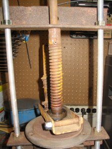
By alternatively tightening the nuts on the pieces of all thread the tension can be removed from the top roll pin. With the tension removed, use a roll pin punch to drive the top roll pin from the shaft. Then alternatively loosen the two nuts until the spring is fully expanded. All the clutch pieces can now be safely disassembled.
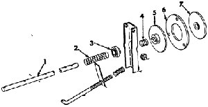
The parts, in order, are:
1. Clutch shaft
Coiled pin
Washer
2. Clutch loading Spring
Washer
3. Throw out bearing
4. Teaser spring
Coil pin
5. Pressure plate hub assembly (moveable)
6. Clutch driving disc
7. Pressure plate hub assembly (fixed)
Coil pin
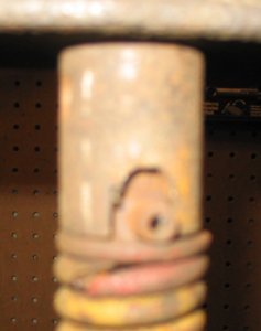
Check the clutch shaft for excessive wear. After years of service there tends to be a lot of wear where the throw out bearing slides on the clutch shaft. Too much wear here will let the throw out bearing hang and prevent the clutch from engaging. If you’ve been having trouble with the clutch “grabbing” it’s probably a worn shaft or a broken teaser spring.
And that’s it. As all the manuals say: reassemble in the reverse order. In most cases that’s not a problem. (Again, if you have trouble replacing the coil pin, read the Coil Pin Removal article under the Tips and Tools section of this website.) As mentioned in the previous discussion the clutch pedal return spring can be a real bear to replace. I really don’t have any good hints here. I’ve always struggled with this and sometimes have luck connecting one end first and at other times have better luck connecting the opposite end first. Enjoy the hobby!!!!!
