Note: When I originally wrote this article, I always used PBlaster as my penatrant of choice. Since then I’ve read a couple scientific investigations that recommend a 50/50 solution of Acetone and ATF (automatic transmission fluid) as a much better, cheaper alternative. As a matter of fact, that solution out performed all popular products currently on the market. I have not updated this article, but that is the penatrant I now use exclusively.
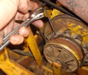
The very first thing to do is to make sure you align the screw holes on the pto with the notches in the basket pulley. Just disengage the pto and rotate the pto pulley until the screw holes line up.
(Lined up hole)
If you forget to do this (I do that a lot) use a pry bar to pry on the button in the center of the pto to release the pressure to allow you to rotate the pulley. A couple of times I’ve placed a v-belt around the motor generator bracket and placed one end of the pry bar in the other end of the v-belt to get leverage.
Removing the PTO is not usually a difficult task but I always plan for the worst. I begin by removing the hood, grill screen and grill housing. It’s only about a 5 minute job. It’s probably not usually necessary, but it’s a lot less frustrating if you run into problems if you’ve already removed everything to make the job easier. And, with the extra room, you’re a lot more apt to do the job correctly. I won’t go through the steps here, since this procedure varies from series to series. (Look in the section on Clutch Removal and Repair for older model Cub Cadets for this procedure.) I do always use anti-seize when replacing the 4 bolts that hold the front grill housing in place. You’ll be glad you did when doing any future work on the tractor.

(Click on Image to Enlarge)
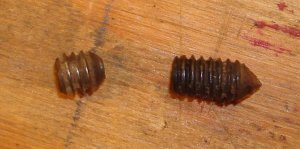
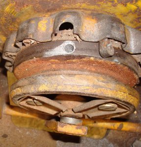
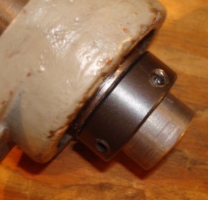
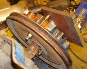
The front pulley is “supposed” to be held on by a ball bearing and six setscrews. I say supposed to be because in a lot of cases a previous owner will have only replaced three of the setscrews – one per hole.
If what’s supposed to be there is there, the outer set “locks” the inner setscrews in place. The inner set crew will have a pointed end to wedge behind the ball bearing that the pto clutch rides on. The
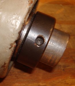
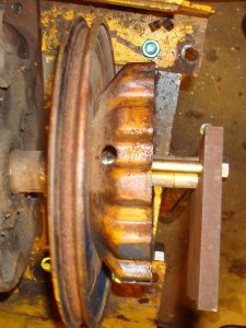
bottom picture on the right side is a picture of the back of a PTO that has been removed. You can see how the point of the setscrew locks the PTO on the bearing. The left picture is supposed to illustrate the same thing, but it’s hard to see with the coarse resolution of the picture.
Removing the setscrews as a rule is the most frustrating and time consuming part of the process. A lot of times they’ll be dirt, mud dobber nests, rust, grease, paint, etc. that has accumulated in the setscrew holes over time. Be sure to clean all this stuff out of the hole and threads and, especially the stuff that’s located in the end of the setscrew. I always use an ice pick to make sure the “hex” hole in the end of the setscrew is completely clean. These set screw are generally hard to break loose, and you want as much of the Allen wrench engaged in the setscrew as possible. After getting all the “gunk” out of the holes, I fill the hole with PBlaster and let it soak 24 hours. You can soak two holes at a time. After letting two holes soak 24 hours, rotate the pto 120 degrees and fill the third hole with PBlaster. I generally put PBlaster in the third hole as well as one that’s previously been soaked. You can’t over soak them!!!
After allowing all the set screws to soak for at least 24 hours, it’s time to remove (or at least try to remove) the setscrews. I buy 1/8” Allen wrenches ten at a time and always start with a new Allen wrench. If you reuse them the corners start to become rounded and they have a tendency to rotate in the hole. I find it much easier to place the long section of the Allen wrench in the hole and use a small adjustable wrench to apply torque to the small end. The small adjustable wrench gives you a better “feel” for how much torque you’re applying to the Allen wrench.
Hopefully, this procedure will remove all the setscrews. The real problem comes when the Allen wrench rotates in one of the setscrews rather then rotating the setscrew. If this happens, you’ll have to drill out the setscrew. Drilling through a setscrew works best with a cobalt bit, lots of cutting fluid and a real, real slow drill speed. Pour a bunch of cutting fluid down the hole with the rounded setscrew and start drilling with a 1/8” cobalt bit. I can’t overemphasize that the drill has to rotate really, really slowly. A fast rotation will cause the drill to overheat and dull. With ample cutting fluid, a good cobalt bit and a slow speed you’ll find that it’s like drilling mild steel. A lot of times the 1/8” bit is sufficient to remove the “tip” of the inner setscrew and allow for removal of the pto clutch. However, I usually follow up with a 3/16” cobalt bit to make sure all the tip is gone. This time you can’t fill the hole with cutting fluid, but again, use a really slow speed. Be careful when you drill all the way through the inner setscrew. Remember that the centerline of the setscrew is just a little behind the outer race of a ball bearing. It’s a good place to snap off the end of a bit. And, always, always use a good coating of antisieze when replacing these set screws. It will make any future repairs a lot easier!!!
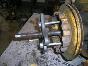
With the setscrews removed it’s time to remove the pto clutch from the ball bearing. Sometimes if you’re lucky you can just wiggle it off or use a plastic mallet for some friendly persuasion. More times then not, however, it won’t come that easily. Some people have reported success by fastening one end of chain around the pulley and whipping the chain. I like a more controlled approach then that, but it does require the use of a large bearing separator which most people don’t own and would have to rent. Begin by placing the bearing puller in the v-belt grooves.
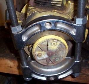

Screw a 3/8” bolt into a 3/8” coupler nut and place it behind one corner of the bearing separator. The length of the bolt varies by engine and where you place it. Ideally, you’ll have the bolt screwed almost all the way into the coupler nut when the combination is just the right length to fit between the bearing separator and engine block. Place another bolt/coupler nut combination between the bearing separator and block on the opposite corner of the first one.
Now use one wrench to keep the bolt from rotating and another wrench to “unscrew” the coupler nut. As you unscrew the coupler nut, the combination becomes longer and pushes the pto clutch off the bearing. Be aware, however, the coupler nut will tend to “walk” sideways as you unscrew it. You’ll have to push on the wrench as you turn the coupler nut to prevent this. It takes a little time and patience but the process is a very controlled means of removing the pto.
Now that the PTO is removed, the bearing has to be removed. The bearing is held on by a locking, eccentric collar.
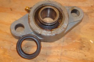
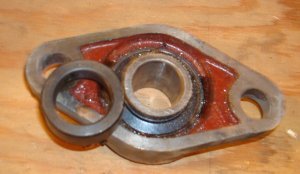
The picture shown is a picture of a flange bearing, but illustrates how the eccentric lock works. Notice in the left picture that the bearing bore has a thin “lip” at the bottom and a much thicker lip at the top. Also, notice that for the collar (bottom left of the picture) there’s a thick and thin portion. (The picture on the right is a picture of the back of the bearing and collar. You can tell everything here is centered. The eccentric is only machined on the outer surface on one side of the bearing.) The bearing is placed on a shaft and the eccentric portion of the collar is slid over the eccentric portion of the bearing. The thin portion of the collar slides over the thick section of the bearing.
As the collar is rotated, it wedges the bearing to the shaft. There’s a circular “depression” in the collar so a punch can be used to rotate it. Simply place the punch in the depression and tap the punch with a hammer to rotate the collar.
Once the collar has been rotated, tighten the setscrew (located in the collar) to hold it in position. Cub Cadet states that to tighten the collar it must be rotated in the direction of engine rotation. So, since the engine rotates in a counterclockwise rotation when viewed from the front of the Cub Cadet, the collar should be rotated in a counterclockwise direction to tighten and a clockwise rotation to loosen. To remove the bearing, begin by loosening the setscrew that holds the collar in place. (For some of the older PTO’s, Cub Cadet put a locking nut on the set screw. If it’s there, loosen it first. Later PTO’s didn’t have the locking nut.) If the PTO has never been removed, place a punch in the depression in the collar and use a hammer to rotate the collar in a clockwise direction. It’s generally pretty obvious when it loosens. If the collar has been previously removed, it may have been rotated in the wrong direction when it was replaced. It just takes trial and error to figure out which way it has to be rotated.
After the collar has been removed, the bearing “should” slide off the end of the shaft. Often the bearing has become stuck on the end of the shaft and won’t just slide off. Sometimes you can remove it by “gently” tapping it with a plastic mallet, but I usually use a small puller to remove them when they’re stuck.
The PTO has been removed!!
Removing the Basket Pulley
Sometimes removing the basket pulley can be a bigger challenge then removing the PTO. Once the PTO has been removed, clean the exposed end of the crankshaft. It there’s any rust on the crankshaft, remove it with fine sand paper. Often the crankshaft is just coated with “gunk”. Remove it with paint thinner or carburetor cleaner.
Begin the process by removing the two setscrews that hold the pulley in place. Remove them and squirt PBlaster in the holes. These pulleys tend to become “set” on the crankshaft over time and the PBlaster will help break them loose. After letting the pulley soak for a while, it’s time to remove it. If you pry on the pulley, you’ll bend it. If you tap on the pulley, you’ll bend it. I begin the process by drilling two 5/16” holes located approximately 2 1/2 inches apart centered on the crankshaft in the basket pulley. You can drill these holes with the pulley on the engine. Start with a small (maybe 1/8”) drill to make a pilot hole before drilling the 3/8” hole.
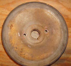
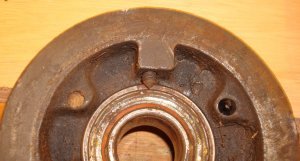
The picture above is a picture of a pulley that has just been removed. Notice there are two holes, one located on each side of the center bore, and located about 2 ½” inches apart. If I get an engine with the pulley already removed, I always drill these two holes before replacing the pulley. It’s easier to drill the holes on the drill press then with the pulley located on the engine.
Now that you have holes drilled in the pulley, drill two 5/16” holes 2 ½ inches apart in a flat piece of steel. Make a puller by placing the flat piece of steel across the end of the crankshaft and using two 5/16” bolts that extend through the pulley. You may have to use some washers to make the distance work out correctly.
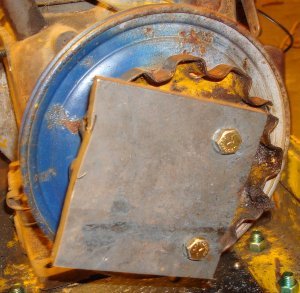
Getting the nuts on the bolts where they extend through the pulley gets a little tricky. But, with a little patience and some long nose pliers it can be done. With all narrow frame Cub Cadets that have a starter/generator, there has to be room behind the basket pulley for clearance of the bolt head that holds the belt adjustment lever in place. That’s enough room to get a nut on the end of the bolt.
When you finish removing the pulley, they’ll be a depression where the 5/16” nut contacts the back of the pulley. But, I’ve never bent a pulley (never say never!!) and the depression is not noticeable from the front of the pulley or when it’s replaced back on the shaft.
As you remove the pulley, you’ll eventually run out of threads, or the basket pulley will come into contact with the flat piece of steel. I always keep some short pieces of aluminum round to use as spacers on the end of the crankshaft for any pulling that I do.
 And that’s it. That’s the procedure I use. If you have some comments or additional ideas, I’d be glad to hear them. Just contact me through cubcadetman.com. Hope you found the article helpful. Enjoy the hobby!!!
Addendum: A fellow Cub Cadet enthusiast sent me some pictures where he modified my procedure and used a harmonic balancer puller instead of having to drill holes in a piece of flat. Here’s a picture of what he did. It looks pretty slick.